
Instruction Manual
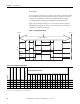
Table Of Contents
- 1769-UM006E-EN-P, Compact High-speed Counter Module User Manual
- Summary of Changes
- Table of Contents
- Preface
- 1 - Module Overview
- 2 - Module Operation
- 3 - Installation and Wiring
- 4 - Module Configuration, Output, and Input Data
- Configure the Module
- Configuration Array
- General Configuration Bits
- Filter Selection
- Program Mode and Program State Run
- Output Program Value (Out0ProgramValue through Out3ProgramValue)
- Output Fault Mode and Output Fault State Run
- Output Fault Value (Out0FaultValue through Out3FaultValue)
- Counter Maximum Count (CtrnMaxCount)
- Counter Minimum Count (CtrnMinCount)
- Counter Preset (CtrnPreset)
- Counter Hysteresis (CtrnHysteresis)
- Counter Scalar (CtrnScalar)
- Cyclic Rate Update Time (CtrnCyclicRateUpdateTime)
- Configuration Flags
- Range High Limit (Range0To11[n].HighLimit) and Range Low Limit (Range0To11[n].LowLimit)
- Range Output Control (Range0To11[n].OutputControl)
- Range Configuration Flags
- Output Array
- Output on Mask (OutputOnMask.0 through OutputOnMask.15)
- Output Off Mask (OutputOffMask.0 through OutputOffMask.15)
- Range Enable (RangeEn.0 through RangeEn.15)
- RBF - Reset Blown Fuse (ResetBlownFuse)
- Control Bits
- Range High Limit or Direct Write Value (Range12To15[n].HiLimOrDirWr)
- Range Low Limit (Range12To15[n].LowLimit)
- Range Output Control (Range12To15[n].OutputControl)
- Range Configuration Flags (12To15)
- Input Array
- Input State (InputStateA0 through InputStateZ1)
- Readback (Readback.0 through Readback.15)
- Status Flags
- Range Active (RangeActive.0 through RangeActive.15)
- Current Count (Ctr[n].CurrentCount)
- Stored Count (Ctr[n].StoredCount)
- Current Rate (Ctr[0].CurrentRate to Ctr[3].CurrentRate)
- Pulse Interval (Ctr[0].PulseInterval and Ctr[1].PulseInterval)
- Status Flags
- 5 - Diagnostics and Troubleshooting
- A - Specifications
- B - Program a 1769-HSC Module, CompactLogix Controller, and 845F Incremental Encoder with RSLogix 5000 Software
- C - Program a 1769-HSC Module, MicroLogix 1500 Controller, and 845F Incremental Encoder with RSLogix 500 Software
- D - Programming Quick Reference
- E - History of Changes
- Glossary
- Index
- Back Cover
40 Rockwell Automation Publication 1769-UM006E-EN-P - July 2013
Chapter 2 Module Operation
Overcurrent
If the module detects a real output point overcurrent condition, it reports it to
the input file and turns off that output. You can also program the module to
latch each of the four real outputs off, emulating a physical fuse, or to
automatically reset. The 12 virtual outputs do not have this function.
When the OvercurrentLatchOff bit is set and an overcurrent situation occurs,
even momentarily, the associated real output is latched off until the
ResetBlownFuse bit transitions from 0 to 1.
If the OvercurrentLatchOff bit is reset and an overcurrent situation occurs, the
output turns off for 1 second and is then retried (auto-reset). The module
continues to attempt to turn the output back on until the overcurrent situation is
no longer detected and the output is successfully turned back on.
Safe State Control
The 1769-HSC module combines the Hold Last State and User-defined Safe
State options with a safe-state run alternative that lets the module to continue to
control outputs under program or fault states
(1)
. These Safe State options are not
available in the packaged controllers.
Only the physical outputs are affected by safe state settings and conditions.
Virtual outputs, inputs, and counting are not affected by program or fault states.
Hold Last State (HLS)
This condition applies depending on the mode of the controller. When the hold
last state option is set, the module holds the outputs at the state they were at just
before the control system transitioned from Run to Program or Run to Fault.
HLS sets the module according to the values configured for Program mode
(described on
page 76) and Output Fault mode (described on page 77).
User-defined Safe State (UDSS)
In this configuration, the module sets the outputs to a user-defined safe state
when the control system transitions from Run to Program or Run to Fault.
UDSS sets the module according to the values configured for Output Program
Value (described on
page 77) and Output Fault Value (described on page 78).
IMPORTANT
The outputs will be on momentarily while they are retried. The length of
time they are on depends on the magnitude of the load.
(1) The module continues to update the input array and count inputs in all modes. The operation of the outputs will
vary according to mode, configuration, and the capabilities of the controller or bus master.