
Instruction Manual
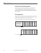
Table Of Contents
- 1769-UM006E-EN-P, Compact High-speed Counter Module User Manual
- Summary of Changes
- Table of Contents
- Preface
- 1 - Module Overview
- 2 - Module Operation
- 3 - Installation and Wiring
- 4 - Module Configuration, Output, and Input Data
- Configure the Module
- Configuration Array
- General Configuration Bits
- Filter Selection
- Program Mode and Program State Run
- Output Program Value (Out0ProgramValue through Out3ProgramValue)
- Output Fault Mode and Output Fault State Run
- Output Fault Value (Out0FaultValue through Out3FaultValue)
- Counter Maximum Count (CtrnMaxCount)
- Counter Minimum Count (CtrnMinCount)
- Counter Preset (CtrnPreset)
- Counter Hysteresis (CtrnHysteresis)
- Counter Scalar (CtrnScalar)
- Cyclic Rate Update Time (CtrnCyclicRateUpdateTime)
- Configuration Flags
- Range High Limit (Range0To11[n].HighLimit) and Range Low Limit (Range0To11[n].LowLimit)
- Range Output Control (Range0To11[n].OutputControl)
- Range Configuration Flags
- Output Array
- Output on Mask (OutputOnMask.0 through OutputOnMask.15)
- Output Off Mask (OutputOffMask.0 through OutputOffMask.15)
- Range Enable (RangeEn.0 through RangeEn.15)
- RBF - Reset Blown Fuse (ResetBlownFuse)
- Control Bits
- Range High Limit or Direct Write Value (Range12To15[n].HiLimOrDirWr)
- Range Low Limit (Range12To15[n].LowLimit)
- Range Output Control (Range12To15[n].OutputControl)
- Range Configuration Flags (12To15)
- Input Array
- Input State (InputStateA0 through InputStateZ1)
- Readback (Readback.0 through Readback.15)
- Status Flags
- Range Active (RangeActive.0 through RangeActive.15)
- Current Count (Ctr[n].CurrentCount)
- Stored Count (Ctr[n].StoredCount)
- Current Rate (Ctr[0].CurrentRate to Ctr[3].CurrentRate)
- Pulse Interval (Ctr[0].PulseInterval and Ctr[1].PulseInterval)
- Status Flags
- 5 - Diagnostics and Troubleshooting
- A - Specifications
- B - Program a 1769-HSC Module, CompactLogix Controller, and 845F Incremental Encoder with RSLogix 5000 Software
- C - Program a 1769-HSC Module, MicroLogix 1500 Controller, and 845F Incremental Encoder with RSLogix 500 Software
- D - Programming Quick Reference
- E - History of Changes
- Glossary
- Index
- Back Cover
42 Rockwell Automation Publication 1769-UM006E-EN-P - July 2013
Chapter 2 Module Operation
Fault State Run (FSR)
Similar to Program State Run, Fault State Run lets you specify, on a bit basis, that
the output should continue to be controlled by the module as if it were Run state.
That is, events on the module or changes in the output image will affect the
physical outputs without regard to the Fault_HLS or UDSS state indicated.
When this bit is set, the corresponding Fault mode and fault value bits are
ignored.
FSR sets the module according to the value configured for Output Fault State
Run, as described on
page 77.
ATTENTION: Selecting this option lets outputs change state while
ladder logic is not running. You must take care to assure that this
does not pose a risk of injury or equipment damage when selecting
this option.
IMPORTANT
The prescan initiated by some controllers can have an effect on the
outputs. To overcome any changes in physical output states caused by
this, use retentive output instructions (for example, latch or unlatch)
when bit manipulations are done on the Output image of this module
in ladder logic.
This applies to a wide range of bits when Fault State Run is selected,
because presetting a counter, enabling a range, changing a mask, and
changing configuration array settings can cause ranges and outputs to
change state.