
Instruction Manual
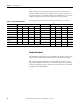
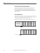
Table Of Contents
- 1769-UM006E-EN-P, Compact High-speed Counter Module User Manual
- Summary of Changes
- Table of Contents
- Preface
- 1 - Module Overview
- 2 - Module Operation
- 3 - Installation and Wiring
- 4 - Module Configuration, Output, and Input Data
- Configure the Module
- Configuration Array
- General Configuration Bits
- Filter Selection
- Program Mode and Program State Run
- Output Program Value (Out0ProgramValue through Out3ProgramValue)
- Output Fault Mode and Output Fault State Run
- Output Fault Value (Out0FaultValue through Out3FaultValue)
- Counter Maximum Count (CtrnMaxCount)
- Counter Minimum Count (CtrnMinCount)
- Counter Preset (CtrnPreset)
- Counter Hysteresis (CtrnHysteresis)
- Counter Scalar (CtrnScalar)
- Cyclic Rate Update Time (CtrnCyclicRateUpdateTime)
- Configuration Flags
- Range High Limit (Range0To11[n].HighLimit) and Range Low Limit (Range0To11[n].LowLimit)
- Range Output Control (Range0To11[n].OutputControl)
- Range Configuration Flags
- Output Array
- Output on Mask (OutputOnMask.0 through OutputOnMask.15)
- Output Off Mask (OutputOffMask.0 through OutputOffMask.15)
- Range Enable (RangeEn.0 through RangeEn.15)
- RBF - Reset Blown Fuse (ResetBlownFuse)
- Control Bits
- Range High Limit or Direct Write Value (Range12To15[n].HiLimOrDirWr)
- Range Low Limit (Range12To15[n].LowLimit)
- Range Output Control (Range12To15[n].OutputControl)
- Range Configuration Flags (12To15)
- Input Array
- Input State (InputStateA0 through InputStateZ1)
- Readback (Readback.0 through Readback.15)
- Status Flags
- Range Active (RangeActive.0 through RangeActive.15)
- Current Count (Ctr[n].CurrentCount)
- Stored Count (Ctr[n].StoredCount)
- Current Rate (Ctr[0].CurrentRate to Ctr[3].CurrentRate)
- Pulse Interval (Ctr[0].PulseInterval and Ctr[1].PulseInterval)
- Status Flags
- 5 - Diagnostics and Troubleshooting
- A - Specifications
- B - Program a 1769-HSC Module, CompactLogix Controller, and 845F Incremental Encoder with RSLogix 5000 Software
- C - Program a 1769-HSC Module, MicroLogix 1500 Controller, and 845F Incremental Encoder with RSLogix 500 Software
- D - Programming Quick Reference
- E - History of Changes
- Glossary
- Index
- Back Cover
44 Rockwell Automation Publication 1769-UM006E-EN-P - July 2013
Chapter 2 Module Operation
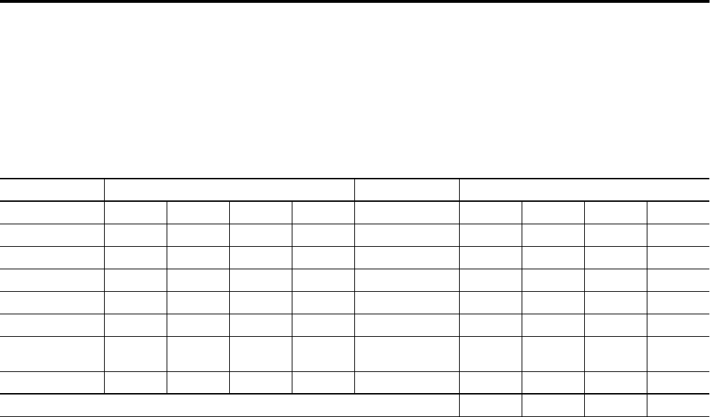
Table 11 illustrates the step-by-step logical operations that are performed to
determine the final output state. For example, Range 1 values do not affect the
output because Range 1 is disabled, and the Output Off Mask causes some of the
outputs to change to zero because it takes priority over the range masks.
The output parameters shown have been discussed in the previous sections.
Readback/Loopback
The Readback/Loopback function is the feedback of the module’s outputs via its
input array. This 16-bit image includes both real (4) and virtual (12) outputs.
If the module’s output is OFF due to overcurrent, both the Overcurrent status
flag and the Readback bit will indicate the condition being 1 and 0, respectively.
Conversely, should the output be ON due to any module control, such as UDSS,
this will be indicated by Readback.
Table 11 - Output Control Example
Output Parameter Mask Information Logical Operation Result
(1)
Range 0 0 001011011010001OR 0001011011010001
Range 1 0 010111111110010OR 0001011011010001
Range 2 0 100000000001100OR 0001011011010001
Output On Mask 0 100101010101000OR 01 011 110111 1 1 001
Output Overcurrent - -----------1000AND 0101111011110 001
Output Off Mask 1 111000011111100AND 0101000011110000
Program State
Values
------------11 1 1 Override 0 101000011110000
Fault State Values - -----------11 1 1 Override 0 101000011110000
Final Output State 0 101000011110000
(1) Bolded text indicates that these values have changed.