
Instruction Manual
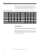
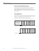
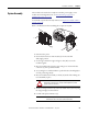
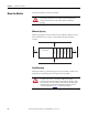
Table Of Contents
- 1769-UM006E-EN-P, Compact High-speed Counter Module User Manual
- Summary of Changes
- Table of Contents
- Preface
- 1 - Module Overview
- 2 - Module Operation
- 3 - Installation and Wiring
- 4 - Module Configuration, Output, and Input Data
- Configure the Module
- Configuration Array
- General Configuration Bits
- Filter Selection
- Program Mode and Program State Run
- Output Program Value (Out0ProgramValue through Out3ProgramValue)
- Output Fault Mode and Output Fault State Run
- Output Fault Value (Out0FaultValue through Out3FaultValue)
- Counter Maximum Count (CtrnMaxCount)
- Counter Minimum Count (CtrnMinCount)
- Counter Preset (CtrnPreset)
- Counter Hysteresis (CtrnHysteresis)
- Counter Scalar (CtrnScalar)
- Cyclic Rate Update Time (CtrnCyclicRateUpdateTime)
- Configuration Flags
- Range High Limit (Range0To11[n].HighLimit) and Range Low Limit (Range0To11[n].LowLimit)
- Range Output Control (Range0To11[n].OutputControl)
- Range Configuration Flags
- Output Array
- Output on Mask (OutputOnMask.0 through OutputOnMask.15)
- Output Off Mask (OutputOffMask.0 through OutputOffMask.15)
- Range Enable (RangeEn.0 through RangeEn.15)
- RBF - Reset Blown Fuse (ResetBlownFuse)
- Control Bits
- Range High Limit or Direct Write Value (Range12To15[n].HiLimOrDirWr)
- Range Low Limit (Range12To15[n].LowLimit)
- Range Output Control (Range12To15[n].OutputControl)
- Range Configuration Flags (12To15)
- Input Array
- Input State (InputStateA0 through InputStateZ1)
- Readback (Readback.0 through Readback.15)
- Status Flags
- Range Active (RangeActive.0 through RangeActive.15)
- Current Count (Ctr[n].CurrentCount)
- Stored Count (Ctr[n].StoredCount)
- Current Rate (Ctr[0].CurrentRate to Ctr[3].CurrentRate)
- Pulse Interval (Ctr[0].PulseInterval and Ctr[1].PulseInterval)
- Status Flags
- 5 - Diagnostics and Troubleshooting
- A - Specifications
- B - Program a 1769-HSC Module, CompactLogix Controller, and 845F Incremental Encoder with RSLogix 5000 Software
- C - Program a 1769-HSC Module, MicroLogix 1500 Controller, and 845F Incremental Encoder with RSLogix 500 Software
- D - Programming Quick Reference
- E - History of Changes
- Glossary
- Index
- Back Cover
Rockwell Automation Publication 1769-UM006E-EN-P - July 2013 47
Installation and Wiring Chapter 3
Power Requirements
The modules receive power through the Compact bus interface from the
5V DC/24V DC system power supply. The maximum current drawn by the
modules is shown in the table.
General Considerations
Compact I/O is suitable for use in an industrial environment when installed in
accordance with these instructions.
Selecting a Location to Reduce Noise
Most applications require installation in an industrial enclosure to reduce the
effects of electrical interference. The module is highly susceptible to electrical
noise. Electrical noise coupled to the inputs will reduce the performance
(accuracy) of the module.
Group your modules to minimize adverse effects from radiated electrical noise
and heat. When selecting a location for a module, position the module away from
the following:
• Sources of electrical noise, such as hard-contact switches, relays, and AC
motor drives.
• Modules that generate significant radiated heat, such as the 1769-IA16
module. Refer to the module’s heat dissipation specification.
In addition, route shielded, twisted-pair analog input and output wiring away
from any high voltage I/O wiring.
Module Current Draw 5V DC 24V DC
425 mA 0 mA
WARNING: When you insert or remove the module while backplane
power is on, an electrical arc can occur. This could cause an explosion in
hazardous location installations.
By sure that power is removed or the area is nonhazardous before
proceeding. Repeated electrical arcing causes excessive wear to contacts on
both the module and its mating connector. Worn contacts can create
electrical resistance that can affect module operation.
WARNING: Removable Terminal Block (RTB) Under Power
When you connect or disconnect the removable terminal block (RTB) with field
side power applied, an electrical arc can occur. This could cause an explosion
in hazardous location installations.
Be sure that power is removed or the area is nonhazardous before proceeding.