
Instruction Manual
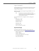
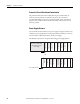
Table Of Contents
- 1769-UM006E-EN-P, Compact High-speed Counter Module User Manual
- Summary of Changes
- Table of Contents
- Preface
- 1 - Module Overview
- 2 - Module Operation
- 3 - Installation and Wiring
- 4 - Module Configuration, Output, and Input Data
- Configure the Module
- Configuration Array
- General Configuration Bits
- Filter Selection
- Program Mode and Program State Run
- Output Program Value (Out0ProgramValue through Out3ProgramValue)
- Output Fault Mode and Output Fault State Run
- Output Fault Value (Out0FaultValue through Out3FaultValue)
- Counter Maximum Count (CtrnMaxCount)
- Counter Minimum Count (CtrnMinCount)
- Counter Preset (CtrnPreset)
- Counter Hysteresis (CtrnHysteresis)
- Counter Scalar (CtrnScalar)
- Cyclic Rate Update Time (CtrnCyclicRateUpdateTime)
- Configuration Flags
- Range High Limit (Range0To11[n].HighLimit) and Range Low Limit (Range0To11[n].LowLimit)
- Range Output Control (Range0To11[n].OutputControl)
- Range Configuration Flags
- Output Array
- Output on Mask (OutputOnMask.0 through OutputOnMask.15)
- Output Off Mask (OutputOffMask.0 through OutputOffMask.15)
- Range Enable (RangeEn.0 through RangeEn.15)
- RBF - Reset Blown Fuse (ResetBlownFuse)
- Control Bits
- Range High Limit or Direct Write Value (Range12To15[n].HiLimOrDirWr)
- Range Low Limit (Range12To15[n].LowLimit)
- Range Output Control (Range12To15[n].OutputControl)
- Range Configuration Flags (12To15)
- Input Array
- Input State (InputStateA0 through InputStateZ1)
- Readback (Readback.0 through Readback.15)
- Status Flags
- Range Active (RangeActive.0 through RangeActive.15)
- Current Count (Ctr[n].CurrentCount)
- Stored Count (Ctr[n].StoredCount)
- Current Rate (Ctr[0].CurrentRate to Ctr[3].CurrentRate)
- Pulse Interval (Ctr[0].PulseInterval and Ctr[1].PulseInterval)
- Status Flags
- 5 - Diagnostics and Troubleshooting
- A - Specifications
- B - Program a 1769-HSC Module, CompactLogix Controller, and 845F Incremental Encoder with RSLogix 5000 Software
- C - Program a 1769-HSC Module, MicroLogix 1500 Controller, and 845F Incremental Encoder with RSLogix 500 Software
- D - Programming Quick Reference
- E - History of Changes
- Glossary
- Index
- Back Cover
Rockwell Automation Publication 1769-UM006E-EN-P - July 2013 49
Installation and Wiring Chapter 3
System Assembly
The module can be attached to an adjacent controller, power supply, or I/O
module. For mounting instructions, see
Panel Mounting on page 50, or
DIN Rail Mounting on page 52.
To work with a system that is already mounted, see
Replace the Module within a
System on page 53.
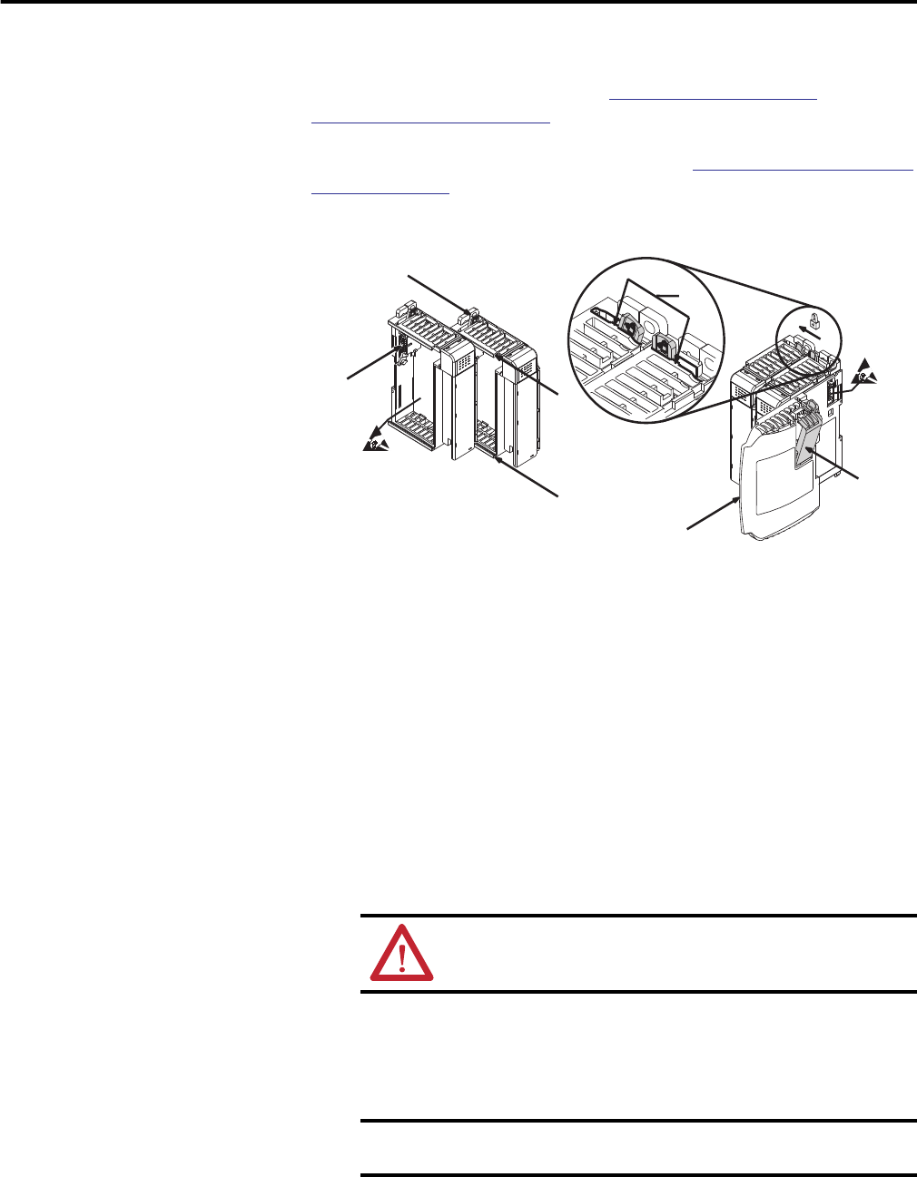
Refer to the illustration when assembling the Compact I/O system.
1. Disconnect the power.
2. Check that the bus lever of the module (A) is in the unlocked
(fully right) position.
3. Use the upper and lower tongue-and-groove slots (B) to secure the
modules together.
4. Move the module back along the tongue-and-groove slots until the bus
connectors (C) line up with each other.
5. Use your fingers or a small screwdriver to push the bus lever back slightly to
clear the positioning tab (D).
6. Move the module’s bus lever fully to the left (E) until it clicks, making sure
it’s locked firmly in place.
7. Attach an end cap terminator (F) to the last module in the system by using
the tongue-and-groove slots as before.
8. Lock the end cap bus terminator (G).
ATTENTION: When attaching I/O modules, it is very important
that the bus connectors are securely locked together to provide
proper electrical connection.
IMPORTANT
A 1769-ECR right- or 1769-ECL left-end cap must be used to
terminate the end of the serial communication bus.
45275
G
F
E
D
B
B
A
C