
Instruction Manual
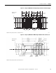
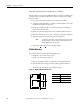
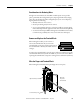
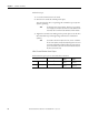
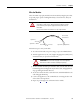
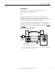
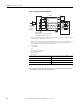
Table Of Contents
- 1769-UM006E-EN-P, Compact High-speed Counter Module User Manual
- Summary of Changes
- Table of Contents
- Preface
- 1 - Module Overview
- 2 - Module Operation
- 3 - Installation and Wiring
- 4 - Module Configuration, Output, and Input Data
- Configure the Module
- Configuration Array
- General Configuration Bits
- Filter Selection
- Program Mode and Program State Run
- Output Program Value (Out0ProgramValue through Out3ProgramValue)
- Output Fault Mode and Output Fault State Run
- Output Fault Value (Out0FaultValue through Out3FaultValue)
- Counter Maximum Count (CtrnMaxCount)
- Counter Minimum Count (CtrnMinCount)
- Counter Preset (CtrnPreset)
- Counter Hysteresis (CtrnHysteresis)
- Counter Scalar (CtrnScalar)
- Cyclic Rate Update Time (CtrnCyclicRateUpdateTime)
- Configuration Flags
- Range High Limit (Range0To11[n].HighLimit) and Range Low Limit (Range0To11[n].LowLimit)
- Range Output Control (Range0To11[n].OutputControl)
- Range Configuration Flags
- Output Array
- Output on Mask (OutputOnMask.0 through OutputOnMask.15)
- Output Off Mask (OutputOffMask.0 through OutputOffMask.15)
- Range Enable (RangeEn.0 through RangeEn.15)
- RBF - Reset Blown Fuse (ResetBlownFuse)
- Control Bits
- Range High Limit or Direct Write Value (Range12To15[n].HiLimOrDirWr)
- Range Low Limit (Range12To15[n].LowLimit)
- Range Output Control (Range12To15[n].OutputControl)
- Range Configuration Flags (12To15)
- Input Array
- Input State (InputStateA0 through InputStateZ1)
- Readback (Readback.0 through Readback.15)
- Status Flags
- Range Active (RangeActive.0 through RangeActive.15)
- Current Count (Ctr[n].CurrentCount)
- Stored Count (Ctr[n].StoredCount)
- Current Rate (Ctr[0].CurrentRate to Ctr[3].CurrentRate)
- Pulse Interval (Ctr[0].PulseInterval and Ctr[1].PulseInterval)
- Status Flags
- 5 - Diagnostics and Troubleshooting
- A - Specifications
- B - Program a 1769-HSC Module, CompactLogix Controller, and 845F Incremental Encoder with RSLogix 5000 Software
- C - Program a 1769-HSC Module, MicroLogix 1500 Controller, and 845F Incremental Encoder with RSLogix 500 Software
- D - Programming Quick Reference
- E - History of Changes
- Glossary
- Index
- Back Cover
52 Rockwell Automation Publication 1769-UM006E-EN-P - July 2013
Chapter 3 Installation and Wiring
Panel Mounting Procedure By Using Modules as a Template
This procedure lets you use the assembled modules as a template for drilling holes
in the panel. Due to module mounting hole tolerance, it is important to follow
these procedures:
1. On a clean work surface, assemble no more than three modules.
2. Using the assembled modules as a template, carefully mark the center of all
module-mounting holes on the panel.
3. Return the assembled modules to the clean work surface, including any
previously mounted modules.
4. Drill and tap the mounting holes for the recommended M4 or #8 screw.
5. Place the modules back on the panel, and check for proper hole alignment.
6. Attach the modules to the panel using the mounting screws.
7. Repeat steps
1 through 6 for any remaining modules.
DIN Rail Mounting
The module can be mounted on the following DIN rails:
• EN 50 022 - 35 x 7.5 mm (1.38 x 0.3 in.)
• EN 50 - 35 x 15 mm (1.38 x 0.59 in.)
1. Before mounting the module on a DIN rail, close the DIN rail latches.
2. Press the DIN rail mounting area of the module against the DIN rail.
The latches will momentarily open and lock into place.
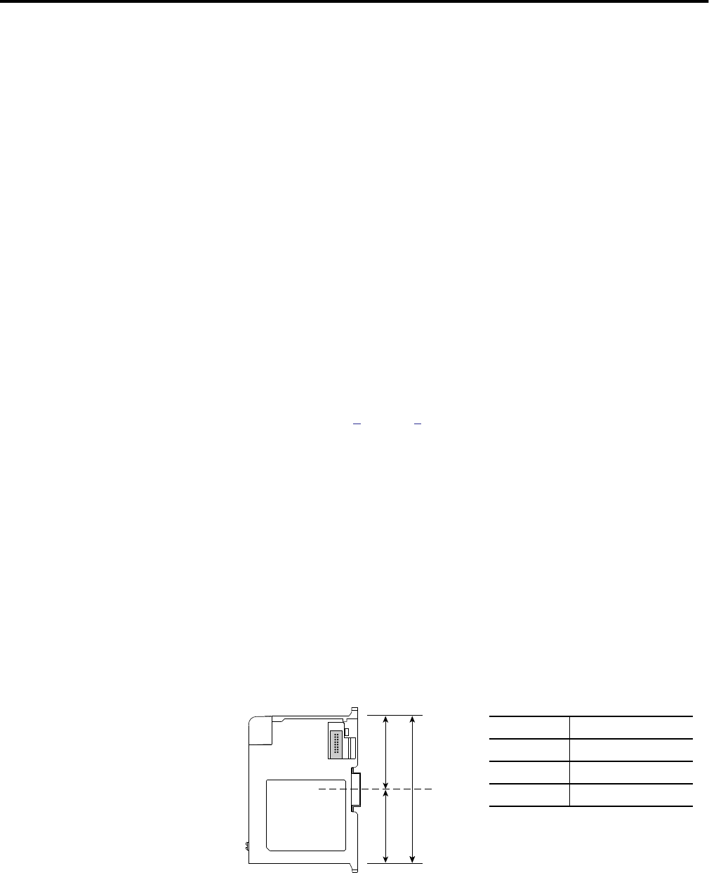
Figure 13 - DIN Rail Mounting Dimensions
TIP
If mounting more modules, mount only the last one of this group
and put the others aside. This reduces remounting time during
drilling and tapping of the next group.
A
B
C
Dimension Height
A 118 mm (4.65 in.)
B 59 mm (2.325 in.)
C 59 mm (2.325 in.)