
Instruction Manual
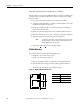
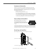
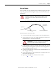
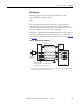
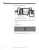
Table Of Contents
- 1769-UM006E-EN-P, Compact High-speed Counter Module User Manual
- Summary of Changes
- Table of Contents
- Preface
- 1 - Module Overview
- 2 - Module Operation
- 3 - Installation and Wiring
- 4 - Module Configuration, Output, and Input Data
- Configure the Module
- Configuration Array
- General Configuration Bits
- Filter Selection
- Program Mode and Program State Run
- Output Program Value (Out0ProgramValue through Out3ProgramValue)
- Output Fault Mode and Output Fault State Run
- Output Fault Value (Out0FaultValue through Out3FaultValue)
- Counter Maximum Count (CtrnMaxCount)
- Counter Minimum Count (CtrnMinCount)
- Counter Preset (CtrnPreset)
- Counter Hysteresis (CtrnHysteresis)
- Counter Scalar (CtrnScalar)
- Cyclic Rate Update Time (CtrnCyclicRateUpdateTime)
- Configuration Flags
- Range High Limit (Range0To11[n].HighLimit) and Range Low Limit (Range0To11[n].LowLimit)
- Range Output Control (Range0To11[n].OutputControl)
- Range Configuration Flags
- Output Array
- Output on Mask (OutputOnMask.0 through OutputOnMask.15)
- Output Off Mask (OutputOffMask.0 through OutputOffMask.15)
- Range Enable (RangeEn.0 through RangeEn.15)
- RBF - Reset Blown Fuse (ResetBlownFuse)
- Control Bits
- Range High Limit or Direct Write Value (Range12To15[n].HiLimOrDirWr)
- Range Low Limit (Range12To15[n].LowLimit)
- Range Output Control (Range12To15[n].OutputControl)
- Range Configuration Flags (12To15)
- Input Array
- Input State (InputStateA0 through InputStateZ1)
- Readback (Readback.0 through Readback.15)
- Status Flags
- Range Active (RangeActive.0 through RangeActive.15)
- Current Count (Ctr[n].CurrentCount)
- Stored Count (Ctr[n].StoredCount)
- Current Rate (Ctr[0].CurrentRate to Ctr[3].CurrentRate)
- Pulse Interval (Ctr[0].PulseInterval and Ctr[1].PulseInterval)
- Status Flags
- 5 - Diagnostics and Troubleshooting
- A - Specifications
- B - Program a 1769-HSC Module, CompactLogix Controller, and 845F Incremental Encoder with RSLogix 5000 Software
- C - Program a 1769-HSC Module, MicroLogix 1500 Controller, and 845F Incremental Encoder with RSLogix 500 Software
- D - Programming Quick Reference
- E - History of Changes
- Glossary
- Index
- Back Cover

Rockwell Automation Publication 1769-UM006E-EN-P - July 2013 53
Installation and Wiring Chapter 3
Replace the Module within
a System
The module can be replaced while the system is mounted to a panel or DIN rail.
1. Remove power, referring to the Warning on
page 47.
2. Remove terminal block or disconnect input and/or output wiring from the
module.
3. Remove the upper and lower mounting screws from the module (or open
the DIN latches using a screwdriver).
4. On the module to be replaced and the right-side adjacent module (or end
cap if the module is the last module in the bank), move the bus levers to the
right (unlock) to disconnect the module from the adjacent modules.
5. Gently slide the disconnected module forward.
If you feel excessive resistance, make sure that you disconnected the
module from the bus and that you removed both mounting screws (or
opened the DIN latches).
6. Before installing the replacement module, be sure that the bus lever on the
right-side adjacent module is in the unlocked (fully-right) position.
7. Slide the replacement module into the open slot.
8. Connect the modules together by locking (fully-left) the bus levers on the
replacement module and the right-side adjacent module or end cap.
9. Replace the mounting screws (or snap the module onto the DIN rail).
10. Replace the terminal block or connect the input and/or output wiring to
the module.
TIP
It may be necessary to rock the module slightly from front
to back to remove it, or, in a panel-mounted system, to
loosen the screws of adjacent modules.