
Instruction Manual
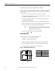
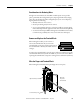
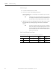
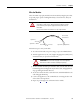
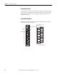
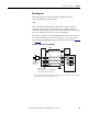
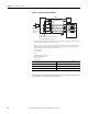
Table Of Contents
- 1769-UM006E-EN-P, Compact High-speed Counter Module User Manual
- Summary of Changes
- Table of Contents
- Preface
- 1 - Module Overview
- 2 - Module Operation
- 3 - Installation and Wiring
- 4 - Module Configuration, Output, and Input Data
- Configure the Module
- Configuration Array
- General Configuration Bits
- Filter Selection
- Program Mode and Program State Run
- Output Program Value (Out0ProgramValue through Out3ProgramValue)
- Output Fault Mode and Output Fault State Run
- Output Fault Value (Out0FaultValue through Out3FaultValue)
- Counter Maximum Count (CtrnMaxCount)
- Counter Minimum Count (CtrnMinCount)
- Counter Preset (CtrnPreset)
- Counter Hysteresis (CtrnHysteresis)
- Counter Scalar (CtrnScalar)
- Cyclic Rate Update Time (CtrnCyclicRateUpdateTime)
- Configuration Flags
- Range High Limit (Range0To11[n].HighLimit) and Range Low Limit (Range0To11[n].LowLimit)
- Range Output Control (Range0To11[n].OutputControl)
- Range Configuration Flags
- Output Array
- Output on Mask (OutputOnMask.0 through OutputOnMask.15)
- Output Off Mask (OutputOffMask.0 through OutputOffMask.15)
- Range Enable (RangeEn.0 through RangeEn.15)
- RBF - Reset Blown Fuse (ResetBlownFuse)
- Control Bits
- Range High Limit or Direct Write Value (Range12To15[n].HiLimOrDirWr)
- Range Low Limit (Range12To15[n].LowLimit)
- Range Output Control (Range12To15[n].OutputControl)
- Range Configuration Flags (12To15)
- Input Array
- Input State (InputStateA0 through InputStateZ1)
- Readback (Readback.0 through Readback.15)
- Status Flags
- Range Active (RangeActive.0 through RangeActive.15)
- Current Count (Ctr[n].CurrentCount)
- Stored Count (Ctr[n].StoredCount)
- Current Rate (Ctr[0].CurrentRate to Ctr[3].CurrentRate)
- Pulse Interval (Ctr[0].PulseInterval and Ctr[1].PulseInterval)
- Status Flags
- 5 - Diagnostics and Troubleshooting
- A - Specifications
- B - Program a 1769-HSC Module, CompactLogix Controller, and 845F Incremental Encoder with RSLogix 5000 Software
- C - Program a 1769-HSC Module, MicroLogix 1500 Controller, and 845F Incremental Encoder with RSLogix 500 Software
- D - Programming Quick Reference
- E - History of Changes
- Glossary
- Index
- Back Cover

56 Rockwell Automation Publication 1769-UM006E-EN-P - July 2013
Chapter 3 Installation and Wiring
Follow these steps.
1. Loosen the terminal screws to be wired.
2. Route the wire under the terminal pressure plate.
You can use the bare wire or a spade lug. The terminals accept a 6.35 mm
(0.25 in.) spade lug.
3. Tighten the terminal screw making sure the pressure plate secures the wire.
Recommended torque when tightening terminal screws is 0.68 N•m
(6 lb•in).
Wire Size and Terminal Screw Torque
Each terminal accepts up to two wires with these restrictions.
TIP
The terminal screws are non-captive. Therefore, it is possible to
use a ring lug (6.35 mm (0.25 in.) maximum outside diameter with
3.53 mm (0.139 in.) minimum inside diameter) with the module.
TIP
If you need to remove the finger-safe cover, insert a screwdriver
into one of the square, wiring holes and gently pry the cover off. If
you wire the terminal block with the finger-safe cover removed,
you will not be able to put it back on the terminal block because
the wires will be in the way.
Wire Type Wire Size Terminal Screw
Torque
RetainingScrew
Torque
Solid Cu-90 °C (194 °F) 0.32... 2.1 mm
2
(22...14 AWG) 0.68 N•m
(6 lb•in)
0.46 N•m
(4.1lb•in)
Stranded Cu-90 °C (194 °F) 0.32... 1.3 mm
2
(22...16 AWG) 0.68 N•m
(6 lb•in)
0.46 N•m
(4.1 lb•in)