
Instruction Manual
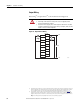
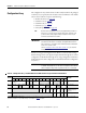
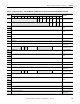
Table Of Contents
- 1769-UM006E-EN-P, Compact High-speed Counter Module User Manual
- Summary of Changes
- Table of Contents
- Preface
- 1 - Module Overview
- 2 - Module Operation
- 3 - Installation and Wiring
- 4 - Module Configuration, Output, and Input Data
- Configure the Module
- Configuration Array
- General Configuration Bits
- Filter Selection
- Program Mode and Program State Run
- Output Program Value (Out0ProgramValue through Out3ProgramValue)
- Output Fault Mode and Output Fault State Run
- Output Fault Value (Out0FaultValue through Out3FaultValue)
- Counter Maximum Count (CtrnMaxCount)
- Counter Minimum Count (CtrnMinCount)
- Counter Preset (CtrnPreset)
- Counter Hysteresis (CtrnHysteresis)
- Counter Scalar (CtrnScalar)
- Cyclic Rate Update Time (CtrnCyclicRateUpdateTime)
- Configuration Flags
- Range High Limit (Range0To11[n].HighLimit) and Range Low Limit (Range0To11[n].LowLimit)
- Range Output Control (Range0To11[n].OutputControl)
- Range Configuration Flags
- Output Array
- Output on Mask (OutputOnMask.0 through OutputOnMask.15)
- Output Off Mask (OutputOffMask.0 through OutputOffMask.15)
- Range Enable (RangeEn.0 through RangeEn.15)
- RBF - Reset Blown Fuse (ResetBlownFuse)
- Control Bits
- Range High Limit or Direct Write Value (Range12To15[n].HiLimOrDirWr)
- Range Low Limit (Range12To15[n].LowLimit)
- Range Output Control (Range12To15[n].OutputControl)
- Range Configuration Flags (12To15)
- Input Array
- Input State (InputStateA0 through InputStateZ1)
- Readback (Readback.0 through Readback.15)
- Status Flags
- Range Active (RangeActive.0 through RangeActive.15)
- Current Count (Ctr[n].CurrentCount)
- Stored Count (Ctr[n].StoredCount)
- Current Rate (Ctr[0].CurrentRate to Ctr[3].CurrentRate)
- Pulse Interval (Ctr[0].PulseInterval and Ctr[1].PulseInterval)
- Status Flags
- 5 - Diagnostics and Troubleshooting
- A - Specifications
- B - Program a 1769-HSC Module, CompactLogix Controller, and 845F Incremental Encoder with RSLogix 5000 Software
- C - Program a 1769-HSC Module, MicroLogix 1500 Controller, and 845F Incremental Encoder with RSLogix 500 Software
- D - Programming Quick Reference
- E - History of Changes
- Glossary
- Index
- Back Cover
Rockwell Automation Publication 1769-UM006E-EN-P - July 2013 61
Installation and Wiring Chapter 3
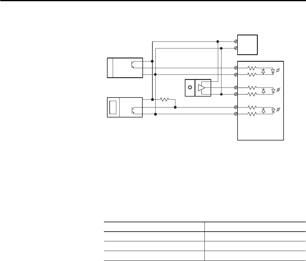
Figure 16 - Discrete Device Wiring
(1)
External resistors are required if they are not internal to the sensor. The pull-up resistor (R) value depends on
the power supply value. The table below shows the maximum resistor values for typical supply voltages. To
calculate the maximum resistor value, use the following formula:
where:
R = maximum pull-up resistor value
VDC = power supply voltage
Vmin = 2.6V DC
Imin = 6.8 mA
The minimum resistor (R) value depends on the current sinking capability of the
sensor. Refer to your sensor’s documentation.
Power Supply Voltage (V DC) Pull-up Resistor Value (R), Max
(1)
(1) Resistance values can change, depending upon your application.
5 352
12 1382
24 3147
VS
A1(+)
A1(–)
B1(+)
B1(–)
Z1(+)
Z1(–)
+VDC
COM
VS
OUT
COM
OUT
COM
VS
OUT
COM
R
(1)
Power
Supply
Module Inputs
Solid-state
Switch
Proximity Sensor
Photo-electric Sensor
with Open Collector
Sinking Output
R
VDC Vmin–
Imin
--------------------------------------------=