
Instruction Manual
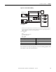
Table Of Contents
- 1769-UM006E-EN-P, Compact High-speed Counter Module User Manual
- Summary of Changes
- Table of Contents
- Preface
- 1 - Module Overview
- 2 - Module Operation
- 3 - Installation and Wiring
- 4 - Module Configuration, Output, and Input Data
- Configure the Module
- Configuration Array
- General Configuration Bits
- Filter Selection
- Program Mode and Program State Run
- Output Program Value (Out0ProgramValue through Out3ProgramValue)
- Output Fault Mode and Output Fault State Run
- Output Fault Value (Out0FaultValue through Out3FaultValue)
- Counter Maximum Count (CtrnMaxCount)
- Counter Minimum Count (CtrnMinCount)
- Counter Preset (CtrnPreset)
- Counter Hysteresis (CtrnHysteresis)
- Counter Scalar (CtrnScalar)
- Cyclic Rate Update Time (CtrnCyclicRateUpdateTime)
- Configuration Flags
- Range High Limit (Range0To11[n].HighLimit) and Range Low Limit (Range0To11[n].LowLimit)
- Range Output Control (Range0To11[n].OutputControl)
- Range Configuration Flags
- Output Array
- Output on Mask (OutputOnMask.0 through OutputOnMask.15)
- Output Off Mask (OutputOffMask.0 through OutputOffMask.15)
- Range Enable (RangeEn.0 through RangeEn.15)
- RBF - Reset Blown Fuse (ResetBlownFuse)
- Control Bits
- Range High Limit or Direct Write Value (Range12To15[n].HiLimOrDirWr)
- Range Low Limit (Range12To15[n].LowLimit)
- Range Output Control (Range12To15[n].OutputControl)
- Range Configuration Flags (12To15)
- Input Array
- Input State (InputStateA0 through InputStateZ1)
- Readback (Readback.0 through Readback.15)
- Status Flags
- Range Active (RangeActive.0 through RangeActive.15)
- Current Count (Ctr[n].CurrentCount)
- Stored Count (Ctr[n].StoredCount)
- Current Rate (Ctr[0].CurrentRate to Ctr[3].CurrentRate)
- Pulse Interval (Ctr[0].PulseInterval and Ctr[1].PulseInterval)
- Status Flags
- 5 - Diagnostics and Troubleshooting
- A - Specifications
- B - Program a 1769-HSC Module, CompactLogix Controller, and 845F Incremental Encoder with RSLogix 5000 Software
- C - Program a 1769-HSC Module, MicroLogix 1500 Controller, and 845F Incremental Encoder with RSLogix 500 Software
- D - Programming Quick Reference
- E - History of Changes
- Glossary
- Index
- Back Cover
64 Rockwell Automation Publication 1769-UM006E-EN-P - July 2013
Chapter 3 Installation and Wiring
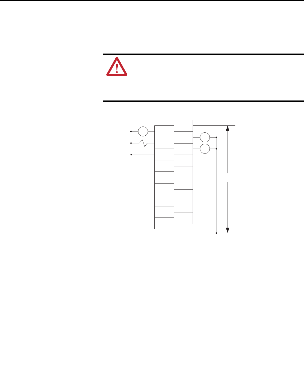
Output Wiring
Basic wiring
(1)
of output devices
(2)
to the module is shown in Figure 18.
Figure 18 - Output Device Wiring
ATTENTION: Follow these guidelines:
• Miswiring of the module to an AC power source or applying reverse
polarity will damage the module.
• Be careful when stripping wires. Wire fragments that fall into a module
could cause damage at powerup. Once wiring is complete, make sure the
module is free of all metal fragments.
(1) Recommended Surge Suppression - The module has built-in suppression which is sufficient for most applications, however, for
high-noise applications, use a 1N4004 diode reverse-wired across the load for transistor outputs switching 24V DC inductive
loads. For additional details, refer to the Industrial Automation Wiring and Grounding Guidelines, publication
1770-4.1.
(2) Sourcing Output - Source describes the current flow between the I/O module and the field device. Sourcing output circuits
supply (source) current to sinking field devices. Field devices connected to the negative side (DC Common) of the field power
supply are sinking field devices. Field devices connected to the positive side (+V) of the field supply are sourcing field devices.
Europe: DC sinking input and sourcing output module circuits are the commonly used options.
45200
CR
OUT 0
OUT 2
OUT
DC COM
A0-
B0-
Z0-
A1-
B1-
Z1-
CR
CR
OUT DC
5/24V DC
OUT 1
OUT 3
A0+
B0+
Z0+
A1+
B1+
Z1+
+DC
-DC
5/24V DC