
Instruction Manual
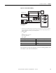
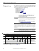
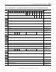
Table Of Contents
- 1769-UM006E-EN-P, Compact High-speed Counter Module User Manual
- Summary of Changes
- Table of Contents
- Preface
- 1 - Module Overview
- 2 - Module Operation
- 3 - Installation and Wiring
- 4 - Module Configuration, Output, and Input Data
- Configure the Module
- Configuration Array
- General Configuration Bits
- Filter Selection
- Program Mode and Program State Run
- Output Program Value (Out0ProgramValue through Out3ProgramValue)
- Output Fault Mode and Output Fault State Run
- Output Fault Value (Out0FaultValue through Out3FaultValue)
- Counter Maximum Count (CtrnMaxCount)
- Counter Minimum Count (CtrnMinCount)
- Counter Preset (CtrnPreset)
- Counter Hysteresis (CtrnHysteresis)
- Counter Scalar (CtrnScalar)
- Cyclic Rate Update Time (CtrnCyclicRateUpdateTime)
- Configuration Flags
- Range High Limit (Range0To11[n].HighLimit) and Range Low Limit (Range0To11[n].LowLimit)
- Range Output Control (Range0To11[n].OutputControl)
- Range Configuration Flags
- Output Array
- Output on Mask (OutputOnMask.0 through OutputOnMask.15)
- Output Off Mask (OutputOffMask.0 through OutputOffMask.15)
- Range Enable (RangeEn.0 through RangeEn.15)
- RBF - Reset Blown Fuse (ResetBlownFuse)
- Control Bits
- Range High Limit or Direct Write Value (Range12To15[n].HiLimOrDirWr)
- Range Low Limit (Range12To15[n].LowLimit)
- Range Output Control (Range12To15[n].OutputControl)
- Range Configuration Flags (12To15)
- Input Array
- Input State (InputStateA0 through InputStateZ1)
- Readback (Readback.0 through Readback.15)
- Status Flags
- Range Active (RangeActive.0 through RangeActive.15)
- Current Count (Ctr[n].CurrentCount)
- Stored Count (Ctr[n].StoredCount)
- Current Rate (Ctr[0].CurrentRate to Ctr[3].CurrentRate)
- Pulse Interval (Ctr[0].PulseInterval and Ctr[1].PulseInterval)
- Status Flags
- 5 - Diagnostics and Troubleshooting
- A - Specifications
- B - Program a 1769-HSC Module, CompactLogix Controller, and 845F Incremental Encoder with RSLogix 5000 Software
- C - Program a 1769-HSC Module, MicroLogix 1500 Controller, and 845F Incremental Encoder with RSLogix 500 Software
- D - Programming Quick Reference
- E - History of Changes
- Glossary
- Index
- Back Cover
Rockwell Automation Publication 1769-UM006E-EN-P - July 2013 65
Chapter 4
Module Configuration, Output, and Input Data
After installing the 1769-HSC module, you must configure it for operation by
using the programming software compatible with the controller, such as
RSLogix 500 or RSLogix 5000 software.
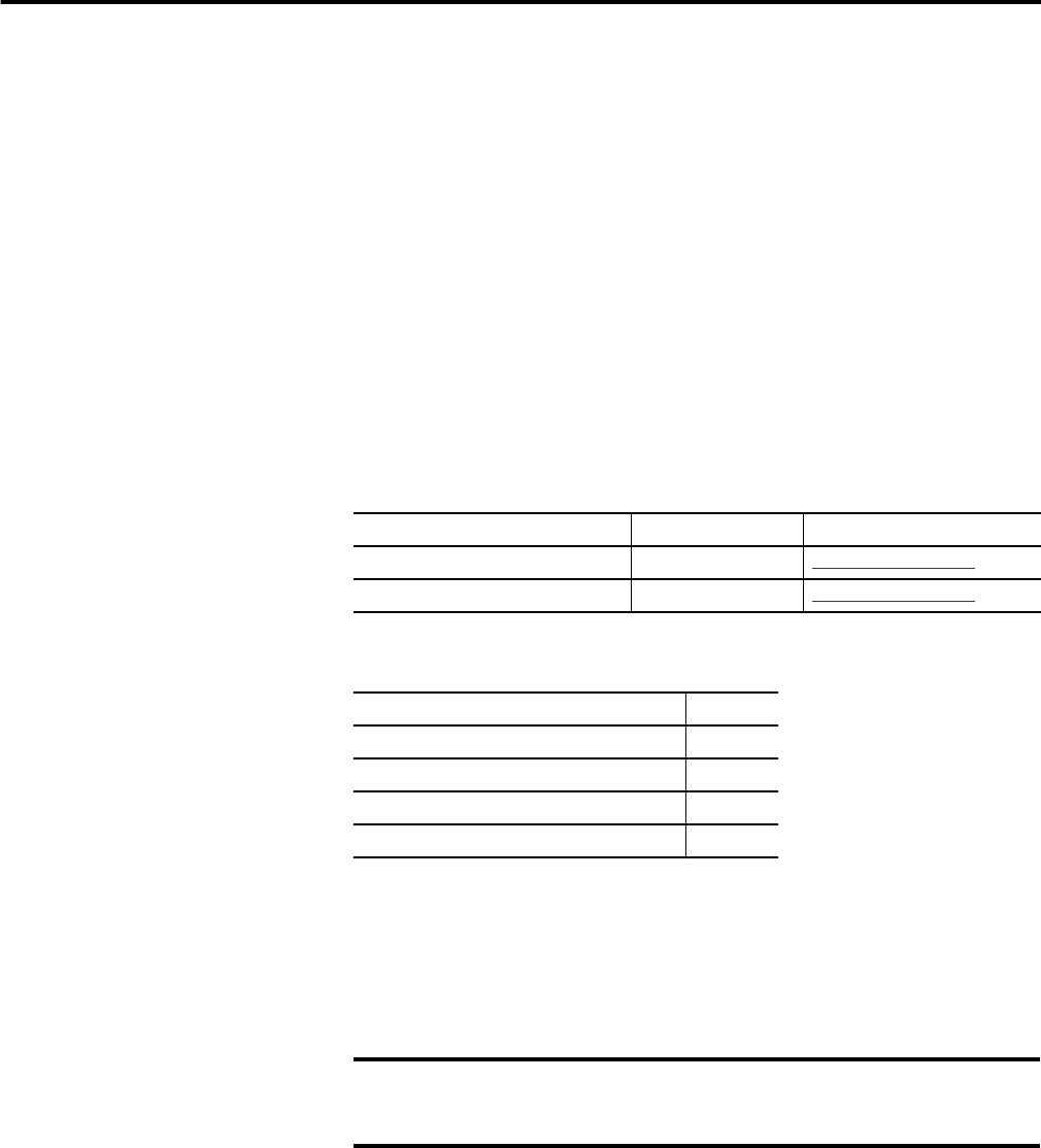
Information on programming the module by using specific controllers and
software is contained in the following appendices.
The table describes the topics in this chapter.
Configure the Module
The module uses three arrays: configuration array, output array, and input array.
You configure the module by establishing settings in the configuration and
output arrays. The input array shows the data that the module sends to the
controller.
TIP
Normal counter configuration is done using programming software. In
that case, it is not necessary to know the meaning of the bit location.
However, some systems let the control program change configuration.
Controller Software See
CompactLogix Controller RSLogix 5000
Appendix B on page 131
MicroLogix 1500 Controller RSLogix 500
Appendix C on page 141
Topic Page
Configure the Module 65
Configuration Array 66
Output Array 88
Input Array 98
IMPORTANT
Both the configuration array and output array settings affect the module
configuration. Changing certain configuration parameters from defaults
can necessitate changing other values to avoid configuration errors.