
Instruction Manual
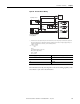
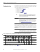
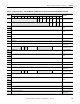
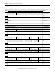
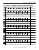
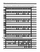
Table Of Contents
- 1769-UM006E-EN-P, Compact High-speed Counter Module User Manual
- Summary of Changes
- Table of Contents
- Preface
- 1 - Module Overview
- 2 - Module Operation
- 3 - Installation and Wiring
- 4 - Module Configuration, Output, and Input Data
- Configure the Module
- Configuration Array
- General Configuration Bits
- Filter Selection
- Program Mode and Program State Run
- Output Program Value (Out0ProgramValue through Out3ProgramValue)
- Output Fault Mode and Output Fault State Run
- Output Fault Value (Out0FaultValue through Out3FaultValue)
- Counter Maximum Count (CtrnMaxCount)
- Counter Minimum Count (CtrnMinCount)
- Counter Preset (CtrnPreset)
- Counter Hysteresis (CtrnHysteresis)
- Counter Scalar (CtrnScalar)
- Cyclic Rate Update Time (CtrnCyclicRateUpdateTime)
- Configuration Flags
- Range High Limit (Range0To11[n].HighLimit) and Range Low Limit (Range0To11[n].LowLimit)
- Range Output Control (Range0To11[n].OutputControl)
- Range Configuration Flags
- Output Array
- Output on Mask (OutputOnMask.0 through OutputOnMask.15)
- Output Off Mask (OutputOffMask.0 through OutputOffMask.15)
- Range Enable (RangeEn.0 through RangeEn.15)
- RBF - Reset Blown Fuse (ResetBlownFuse)
- Control Bits
- Range High Limit or Direct Write Value (Range12To15[n].HiLimOrDirWr)
- Range Low Limit (Range12To15[n].LowLimit)
- Range Output Control (Range12To15[n].OutputControl)
- Range Configuration Flags (12To15)
- Input Array
- Input State (InputStateA0 through InputStateZ1)
- Readback (Readback.0 through Readback.15)
- Status Flags
- Range Active (RangeActive.0 through RangeActive.15)
- Current Count (Ctr[n].CurrentCount)
- Stored Count (Ctr[n].StoredCount)
- Current Rate (Ctr[0].CurrentRate to Ctr[3].CurrentRate)
- Pulse Interval (Ctr[0].PulseInterval and Ctr[1].PulseInterval)
- Status Flags
- 5 - Diagnostics and Troubleshooting
- A - Specifications
- B - Program a 1769-HSC Module, CompactLogix Controller, and 845F Incremental Encoder with RSLogix 5000 Software
- C - Program a 1769-HSC Module, MicroLogix 1500 Controller, and 845F Incremental Encoder with RSLogix 500 Software
- D - Programming Quick Reference
- E - History of Changes
- Glossary
- Index
- Back Cover
66 Rockwell Automation Publication 1769-UM006E-EN-P - July 2013
Chapter 4 Module Configuration, Output, and Input Data
Configuration Array
The configuration array, which consists of 118 words (46 words for the packaged
controller), lets you specify how the module’s counters will function. The default
value is all zeros with the exception of the following:
• NumberofCounters (see
page 75)
• CtrnMaxCount (see
page 78)
• CtrnMinCount (see
page 79)
• CtrnScalar (see
page 80)
• CtrnCyclicUpdateTime (see
page 81)
Word 0 contains general configuration bits. Word 1 contains the filter settings.
Words 2 through 5 refer to the physical outputs. Words 6 through 45 are counter
configuration words. Words 46 through 117 are range configuration words. More
detailed descriptions of the configuration words and bits follow the configuration
array below.
TIP
Normal counter configuration is done using programming software. In
that case, it is not necessary to know the bit location. However, some
systems let the control program change configuration. Refer to your
controller’s documentation for details.
IMPORTANT
When changing configuration values, verify that only valid configurations
are created for the module. For example, changing NumberofCounters
from its default of 1 to 0 requires that Ctr1MinCount and Ctr1MaxCount
also be set to 0, and so forth.
See the Configuration Error Codes table on page 117 if you encounter
configuration errors.
IMPORTANT
Certain values (noted below) cannot be changed while a counter or range
is enabled. Attempting to do so will cause a configuration error and the
entire configuration array will be rejected until the error is eliminated.
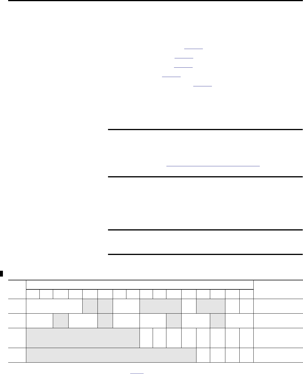
Table 12 - Configuration Array - 1769-HSC Module and CMX 5370 L2 Packaged Controller Embedded HSC
Word
Bit
Function
15 14 13 12 11 10 09 08 07 06 05 04 03 02 01 00
0 Individual Counter Reset
Disable
(1)
NumberOf
Counters
Not used PFE Not used Ctr
Rst
OCL
O
General Configuration
Bits
1 Filter_Z1
Not
used
Filter_B1 Not
used
Filter_A1 Filter_Z0 Not
used
Filter_B0 Not
used
Filter_A0 Filter Selection
2
Not used Out
3
PSR
Out
2
PSR
Out1
PSR
Out0
PSR
Out3
PM
Out2
PM
Out1
PM
Out0
PM
Output Program Mode
and Output Program
State Run
3
Not used Out3
PV
Out2
PV
Out1
PV
Out0
PV
Output Program Value
(1)
For the 1769-HSC/B module only. Bit 12 is Counter 0 reset disable; Bit 13, Counter 1 reset disable; Bit 14, Counter 2 reset disable; Bit 15, Counter 3 reset disable.
Counter reset function = 0: reset enable (default), 1: reset disable. See page 73 for details.