
Instruction Manual
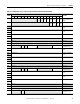
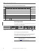
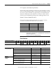
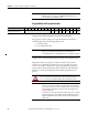
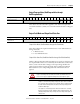
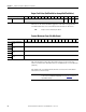
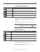
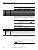
Table Of Contents
- 1769-UM006E-EN-P, Compact High-speed Counter Module User Manual
- Summary of Changes
- Table of Contents
- Preface
- 1 - Module Overview
- 2 - Module Operation
- 3 - Installation and Wiring
- 4 - Module Configuration, Output, and Input Data
- Configure the Module
- Configuration Array
- General Configuration Bits
- Filter Selection
- Program Mode and Program State Run
- Output Program Value (Out0ProgramValue through Out3ProgramValue)
- Output Fault Mode and Output Fault State Run
- Output Fault Value (Out0FaultValue through Out3FaultValue)
- Counter Maximum Count (CtrnMaxCount)
- Counter Minimum Count (CtrnMinCount)
- Counter Preset (CtrnPreset)
- Counter Hysteresis (CtrnHysteresis)
- Counter Scalar (CtrnScalar)
- Cyclic Rate Update Time (CtrnCyclicRateUpdateTime)
- Configuration Flags
- Range High Limit (Range0To11[n].HighLimit) and Range Low Limit (Range0To11[n].LowLimit)
- Range Output Control (Range0To11[n].OutputControl)
- Range Configuration Flags
- Output Array
- Output on Mask (OutputOnMask.0 through OutputOnMask.15)
- Output Off Mask (OutputOffMask.0 through OutputOffMask.15)
- Range Enable (RangeEn.0 through RangeEn.15)
- RBF - Reset Blown Fuse (ResetBlownFuse)
- Control Bits
- Range High Limit or Direct Write Value (Range12To15[n].HiLimOrDirWr)
- Range Low Limit (Range12To15[n].LowLimit)
- Range Output Control (Range12To15[n].OutputControl)
- Range Configuration Flags (12To15)
- Input Array
- Input State (InputStateA0 through InputStateZ1)
- Readback (Readback.0 through Readback.15)
- Status Flags
- Range Active (RangeActive.0 through RangeActive.15)
- Current Count (Ctr[n].CurrentCount)
- Stored Count (Ctr[n].StoredCount)
- Current Rate (Ctr[0].CurrentRate to Ctr[3].CurrentRate)
- Pulse Interval (Ctr[0].PulseInterval and Ctr[1].PulseInterval)
- Status Flags
- 5 - Diagnostics and Troubleshooting
- A - Specifications
- B - Program a 1769-HSC Module, CompactLogix Controller, and 845F Incremental Encoder with RSLogix 5000 Software
- C - Program a 1769-HSC Module, MicroLogix 1500 Controller, and 845F Incremental Encoder with RSLogix 500 Software
- D - Programming Quick Reference
- E - History of Changes
- Glossary
- Index
- Back Cover
72 Rockwell Automation Publication 1769-UM006E-EN-P - July 2013
Chapter 4 Module Configuration, Output, and Input Data
General Configuration Bits
These configuration bits apply to the 1769-HSC/B module and the CMX 5370
L2 packaged controller embedded HSC.
OCLO - Overcurrent Latch Off (OverCurrentLatchOff)
When set, this bit causes the module to make any overcurrent activity latch the
corresponding output off, simulating a physical fuse. When OCLO = 0, it
automatically resets. The rising edge of RBF resets the output.
36 Ctr3MaxCount Counter 3 Maximum
Count
37
38 Ctr3MinCount Counter 3 Minimum
Count
39
40 Ctr3Preset Counter 3 Preset
41
42
Not used Not used
43 Not used Not used
44 Not used Not used
45
Not used Lin-
ear
Not used Counter 3
Configuration Flags
Table 13 - Configuration Array - L23E Packaged Controller Embedded HSC (Continued)
Word
Bit
Function
15 14 13 12 11 10 09 08 07 06 05 04 03 02 01 00
Configuration Array Word 0 15 14 13 12 11 10 09 08 07 06 05 04 03 02 01 00
General Configuration Bits Individual Counter
Reset Disable
(1)
Number of counters Not used PFE Not used Ctr
Reset
OCL
O
(1) For the 1769-HSC/B module only. Bit 12 is Counter 0 reset disable; Bit 13, Counter 1 reset disable; Bit 14, Counter 2 reset disable; Bit 15, Counter 3 reset disable.
Counter reset function = 0: reset enable (default), 1: reset disable. The 1769-HSC/A module does not use bits 12…15 in the configuration array. See page 73
for details.
IMPORTANT
Do not set this bit while a counter or range is enabled (Ctr0En, Ctr1En,
Ctr2En, Ctr3En, or RangeEn set to 1). Attempting to do so will result in a
BadModConfigUpdate error.
See page 120 for a list of prohibited settings.