
Instruction Manual
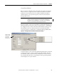
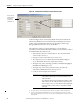
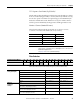
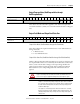
Table Of Contents
- 1769-UM006E-EN-P, Compact High-speed Counter Module User Manual
- Summary of Changes
- Table of Contents
- Preface
- 1 - Module Overview
- 2 - Module Operation
- 3 - Installation and Wiring
- 4 - Module Configuration, Output, and Input Data
- Configure the Module
- Configuration Array
- General Configuration Bits
- Filter Selection
- Program Mode and Program State Run
- Output Program Value (Out0ProgramValue through Out3ProgramValue)
- Output Fault Mode and Output Fault State Run
- Output Fault Value (Out0FaultValue through Out3FaultValue)
- Counter Maximum Count (CtrnMaxCount)
- Counter Minimum Count (CtrnMinCount)
- Counter Preset (CtrnPreset)
- Counter Hysteresis (CtrnHysteresis)
- Counter Scalar (CtrnScalar)
- Cyclic Rate Update Time (CtrnCyclicRateUpdateTime)
- Configuration Flags
- Range High Limit (Range0To11[n].HighLimit) and Range Low Limit (Range0To11[n].LowLimit)
- Range Output Control (Range0To11[n].OutputControl)
- Range Configuration Flags
- Output Array
- Output on Mask (OutputOnMask.0 through OutputOnMask.15)
- Output Off Mask (OutputOffMask.0 through OutputOffMask.15)
- Range Enable (RangeEn.0 through RangeEn.15)
- RBF - Reset Blown Fuse (ResetBlownFuse)
- Control Bits
- Range High Limit or Direct Write Value (Range12To15[n].HiLimOrDirWr)
- Range Low Limit (Range12To15[n].LowLimit)
- Range Output Control (Range12To15[n].OutputControl)
- Range Configuration Flags (12To15)
- Input Array
- Input State (InputStateA0 through InputStateZ1)
- Readback (Readback.0 through Readback.15)
- Status Flags
- Range Active (RangeActive.0 through RangeActive.15)
- Current Count (Ctr[n].CurrentCount)
- Stored Count (Ctr[n].StoredCount)
- Current Rate (Ctr[0].CurrentRate to Ctr[3].CurrentRate)
- Pulse Interval (Ctr[0].PulseInterval and Ctr[1].PulseInterval)
- Status Flags
- 5 - Diagnostics and Troubleshooting
- A - Specifications
- B - Program a 1769-HSC Module, CompactLogix Controller, and 845F Incremental Encoder with RSLogix 5000 Software
- C - Program a 1769-HSC Module, MicroLogix 1500 Controller, and 845F Incremental Encoder with RSLogix 500 Software
- D - Programming Quick Reference
- E - History of Changes
- Glossary
- Index
- Back Cover
74 Rockwell Automation Publication 1769-UM006E-EN-P - July 2013
Chapter 4 Module Configuration, Output, and Input Data
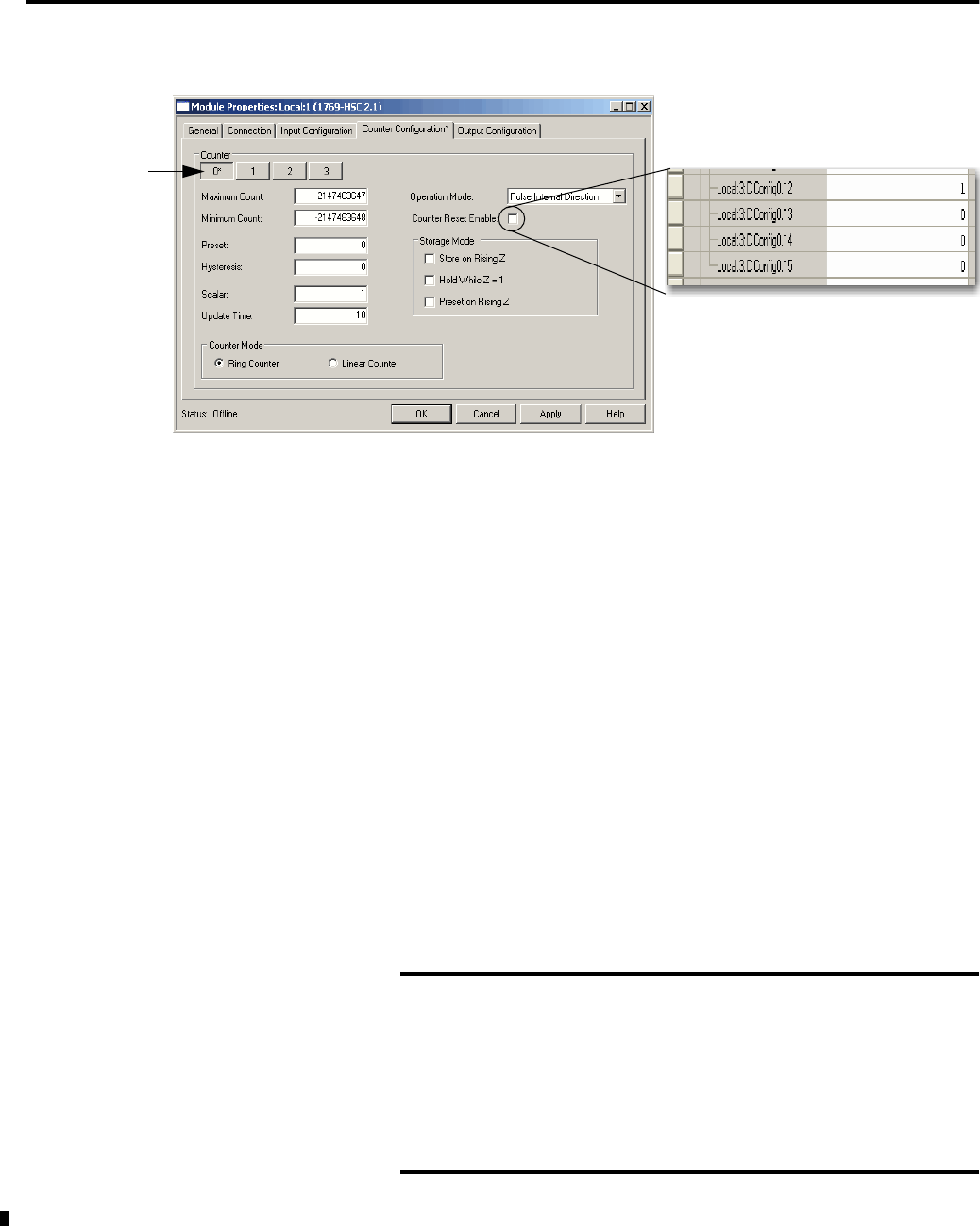
Figure 20 - Configuration for Individual Counter Reset Disable
As shown in Figure 20, the Counter Reset Enable box has been unchecked to
indicate the individual counter reset functionality is disabled for the selected
counter of the 1769-HSC/B module. The corresponding controller tag in
RSLogix 5000 software shows a one (1) for disabled.
The CtrReset bit, when set, causes the following to occur for both the
1769-HSC/A and 1769-HSC/B modules when the system transitions to Run or
the Inhibit Module bit transitions to 0:
• System checks counter reset selection bits 12…15 to determine which
counter needs to be reset.
(1)
• Only those counters selected for reset are reset to zero.
• The output array is reset to default values until the ModConfig bit is
set (1). The default value for the output array is all zeros.
• The input array counter status flags (Overflow, Underflow, RisingEdgeZ,
RateValid, PresetWarning) are reset.
• The input array counter values (Current Count
(2)
, StoredCount,
CurrentRate and PulseInterval) are also reset to zero.
• Counts are lost and outputs are turned off.
Counter 0 in this
example equates
to individual
counter reset
selection bit 12.
(1) This applies only to the 1769-HSC/B module and the CMX 5370 L2 packaged controller embedded HSC.
(2) If zero is outside the MinCount and MaxCount limits set in the configuration array, then the Preset value is
loaded into CurrentCount instead of zero. This also causes the PresetWarning bit to be set, which, in turn, sets
the GenError bit.
IMPORTANT
For most predictable results, clear the output image of the
controller before performing a counter reset (CtrReset) to the
1769-HSC module.
This is because CtrReset does not change the controller’s output
image. CtrReset sets the 1769-HSC module’s output array to all
zeroes. If any bit is set to 1 in the controller’s output image when
sent to the module, it will be seen as a state transition and be
acted upon.