
Instruction Manual
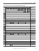
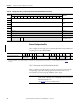
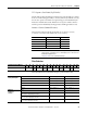
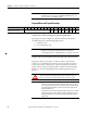
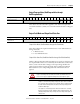
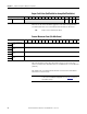
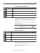
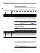
Table Of Contents
- 1769-UM006E-EN-P, Compact High-speed Counter Module User Manual
- Summary of Changes
- Table of Contents
- Preface
- 1 - Module Overview
- 2 - Module Operation
- 3 - Installation and Wiring
- 4 - Module Configuration, Output, and Input Data
- Configure the Module
- Configuration Array
- General Configuration Bits
- Filter Selection
- Program Mode and Program State Run
- Output Program Value (Out0ProgramValue through Out3ProgramValue)
- Output Fault Mode and Output Fault State Run
- Output Fault Value (Out0FaultValue through Out3FaultValue)
- Counter Maximum Count (CtrnMaxCount)
- Counter Minimum Count (CtrnMinCount)
- Counter Preset (CtrnPreset)
- Counter Hysteresis (CtrnHysteresis)
- Counter Scalar (CtrnScalar)
- Cyclic Rate Update Time (CtrnCyclicRateUpdateTime)
- Configuration Flags
- Range High Limit (Range0To11[n].HighLimit) and Range Low Limit (Range0To11[n].LowLimit)
- Range Output Control (Range0To11[n].OutputControl)
- Range Configuration Flags
- Output Array
- Output on Mask (OutputOnMask.0 through OutputOnMask.15)
- Output Off Mask (OutputOffMask.0 through OutputOffMask.15)
- Range Enable (RangeEn.0 through RangeEn.15)
- RBF - Reset Blown Fuse (ResetBlownFuse)
- Control Bits
- Range High Limit or Direct Write Value (Range12To15[n].HiLimOrDirWr)
- Range Low Limit (Range12To15[n].LowLimit)
- Range Output Control (Range12To15[n].OutputControl)
- Range Configuration Flags (12To15)
- Input Array
- Input State (InputStateA0 through InputStateZ1)
- Readback (Readback.0 through Readback.15)
- Status Flags
- Range Active (RangeActive.0 through RangeActive.15)
- Current Count (Ctr[n].CurrentCount)
- Stored Count (Ctr[n].StoredCount)
- Current Rate (Ctr[0].CurrentRate to Ctr[3].CurrentRate)
- Pulse Interval (Ctr[0].PulseInterval and Ctr[1].PulseInterval)
- Status Flags
- 5 - Diagnostics and Troubleshooting
- A - Specifications
- B - Program a 1769-HSC Module, CompactLogix Controller, and 845F Incremental Encoder with RSLogix 5000 Software
- C - Program a 1769-HSC Module, MicroLogix 1500 Controller, and 845F Incremental Encoder with RSLogix 500 Software
- D - Programming Quick Reference
- E - History of Changes
- Glossary
- Index
- Back Cover

Rockwell Automation Publication 1769-UM006E-EN-P - July 2013 75
Module Configuration, Output, and Input Data Chapter 4
PFE - Program to Fault Enable (ProgToFaultEn)
This bit indicates what should happen when the bus controller indicates a change
from one condition (Program mode) to another (Fault mode). If this bit is set (1),
the safe state operation of all four real outputs changes to that identified by the
Fault State and Fault Value words. If this bit is reset (0), the module continues
with the operation identified by the Program State and Program Value words.
Number of Counters (NumberOfCounters)
This 2-bit value indicates whether the module uses 1 counter, 2 counters,
3 counters, or 4 counters. The default value is 1 (2 counters).
Filter Selection
This value indicates the nominal filter frequency as shown in the table.
Bit 01 Bit 00 Counters
001
012
103
114
IMPORTANT
Do not set this value while a counter or range is enabled (Ctr0En, Ctr1En,
Ctr2En, Ctr3En, or RangeEn set to 1). Attempting to do so will result in a
BadModConfigUpdate error.
See page 120 for a list of prohibited settings.
Configuration Array Word 1 15 14 13 12 11 10 09 08 07 06 05 04 03 02 01 00
Filter Selection Filter_Z1
Not
used
FilterB1 Not
used
FilterA1 FilterZ0 Not
used
FilterB0 Not
used
FilterA0
Filters and
Corresponding Bits
FilterA0 Bit 1 - FilterA0_1 Bit 0 - FilterA0_0
FilterB0 Bit 4 - FilterB0_1 Bit 3 - FilterB0_0
FilterZ0 Bit 7 - FilterZ0_1 Bit 6 - FilterZ0_0
FilterA1 Bit 9 - FilterA1_1 Bit 8 - FilterA1_0
FilterB1 Bit 12 - FilterB1_1 Bit 11 - FilterB1_0
FilterZ1 Bit 15 - FilterZ1_1 Bit 14 - FilterZ1_0
Nominal
Frequency
Settings
None 0 0
0.01 ms minimum pulse width
(0.0185 ms for the packaged controller)
01
0.5 ms minimum pulse width
(0.715 ms for the packaged controller)
10
5 ms minimum pulse width
(7.1 ms for the packaged controller)
11