
Instruction Manual
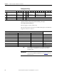
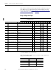
Table Of Contents
- 1769-UM006E-EN-P, Compact High-speed Counter Module User Manual
- Summary of Changes
- Table of Contents
- Preface
- 1 - Module Overview
- 2 - Module Operation
- 3 - Installation and Wiring
- 4 - Module Configuration, Output, and Input Data
- Configure the Module
- Configuration Array
- General Configuration Bits
- Filter Selection
- Program Mode and Program State Run
- Output Program Value (Out0ProgramValue through Out3ProgramValue)
- Output Fault Mode and Output Fault State Run
- Output Fault Value (Out0FaultValue through Out3FaultValue)
- Counter Maximum Count (CtrnMaxCount)
- Counter Minimum Count (CtrnMinCount)
- Counter Preset (CtrnPreset)
- Counter Hysteresis (CtrnHysteresis)
- Counter Scalar (CtrnScalar)
- Cyclic Rate Update Time (CtrnCyclicRateUpdateTime)
- Configuration Flags
- Range High Limit (Range0To11[n].HighLimit) and Range Low Limit (Range0To11[n].LowLimit)
- Range Output Control (Range0To11[n].OutputControl)
- Range Configuration Flags
- Output Array
- Output on Mask (OutputOnMask.0 through OutputOnMask.15)
- Output Off Mask (OutputOffMask.0 through OutputOffMask.15)
- Range Enable (RangeEn.0 through RangeEn.15)
- RBF - Reset Blown Fuse (ResetBlownFuse)
- Control Bits
- Range High Limit or Direct Write Value (Range12To15[n].HiLimOrDirWr)
- Range Low Limit (Range12To15[n].LowLimit)
- Range Output Control (Range12To15[n].OutputControl)
- Range Configuration Flags (12To15)
- Input Array
- Input State (InputStateA0 through InputStateZ1)
- Readback (Readback.0 through Readback.15)
- Status Flags
- Range Active (RangeActive.0 through RangeActive.15)
- Current Count (Ctr[n].CurrentCount)
- Stored Count (Ctr[n].StoredCount)
- Current Rate (Ctr[0].CurrentRate to Ctr[3].CurrentRate)
- Pulse Interval (Ctr[0].PulseInterval and Ctr[1].PulseInterval)
- Status Flags
- 5 - Diagnostics and Troubleshooting
- A - Specifications
- B - Program a 1769-HSC Module, CompactLogix Controller, and 845F Incremental Encoder with RSLogix 5000 Software
- C - Program a 1769-HSC Module, MicroLogix 1500 Controller, and 845F Incremental Encoder with RSLogix 500 Software
- D - Programming Quick Reference
- E - History of Changes
- Glossary
- Index
- Back Cover
Rockwell Automation Publication 1769-UM006E-EN-P - July 2013 83
Module Configuration, Output, and Input Data Chapter 4
Storage Mode (CtrnConfig.StorageMode_0 through
Ctr
nConfig.StorageMode_2)
These three bits apply to Counters 0 and 1 only. They define how the module
interprets the Z input, as shown below. Each bit works independently. If bit 0 and
bit 2 are set simultaneously, a Z event causes the Current Count Value to be
stored and then preset.
Linear (Ctr0Config.Linear through Ctr3Config.Linear)
This bit indicates how the counter operates upon reaching a CtrnMinCount or
CtrnMaxCount.
• 0 = Ring Counter
• 1 = Linear Counter
See
page 28 for a description of ring and linear counter operation.
Set bit For function
CtrnConfig.StorageMode_0 Stores the Current Count Value on the rising edge of Z to
Ctr[n].StoredCount in the input file.
CtrnConfig.StorageMode_1 Holds the counter at its Current Count Value whileZ=1.
CtrnConfig.StorageMode_2 Presets the Current Count Value on the rising edge of Z.
IMPORTANT
Z = internal Z. Internal Z is the version of the Z input pin as modified by
the output array control bits Z Invert and Z Inhibit.
TIP
The Ctr1Config.Storage Mode bits are reserved if NumberofCounters_1
and NumberofCounters_0 are set to 00 (one counter). Attempting to set
reserved bits will result in a configuration error.
IMPORTANT
Do not change this value while the counter is enabled. Attempting to do
so will result in a BadModConfigUpdate error. See page 120 for a list
of prohibited settings.
IMPORTANT
Do not change this value while the counter is enabled. Attempting to do
so will result in a BadModConfigUpdate error. See page 120 for a list of
prohibited settings.