
Instruction Manual
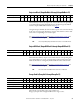
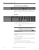
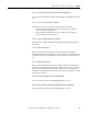
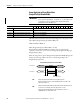
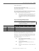
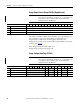
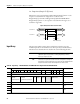
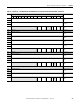
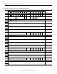
Table Of Contents
- 1769-UM006E-EN-P, Compact High-speed Counter Module User Manual
- Summary of Changes
- Table of Contents
- Preface
- 1 - Module Overview
- 2 - Module Operation
- 3 - Installation and Wiring
- 4 - Module Configuration, Output, and Input Data
- Configure the Module
- Configuration Array
- General Configuration Bits
- Filter Selection
- Program Mode and Program State Run
- Output Program Value (Out0ProgramValue through Out3ProgramValue)
- Output Fault Mode and Output Fault State Run
- Output Fault Value (Out0FaultValue through Out3FaultValue)
- Counter Maximum Count (CtrnMaxCount)
- Counter Minimum Count (CtrnMinCount)
- Counter Preset (CtrnPreset)
- Counter Hysteresis (CtrnHysteresis)
- Counter Scalar (CtrnScalar)
- Cyclic Rate Update Time (CtrnCyclicRateUpdateTime)
- Configuration Flags
- Range High Limit (Range0To11[n].HighLimit) and Range Low Limit (Range0To11[n].LowLimit)
- Range Output Control (Range0To11[n].OutputControl)
- Range Configuration Flags
- Output Array
- Output on Mask (OutputOnMask.0 through OutputOnMask.15)
- Output Off Mask (OutputOffMask.0 through OutputOffMask.15)
- Range Enable (RangeEn.0 through RangeEn.15)
- RBF - Reset Blown Fuse (ResetBlownFuse)
- Control Bits
- Range High Limit or Direct Write Value (Range12To15[n].HiLimOrDirWr)
- Range Low Limit (Range12To15[n].LowLimit)
- Range Output Control (Range12To15[n].OutputControl)
- Range Configuration Flags (12To15)
- Input Array
- Input State (InputStateA0 through InputStateZ1)
- Readback (Readback.0 through Readback.15)
- Status Flags
- Range Active (RangeActive.0 through RangeActive.15)
- Current Count (Ctr[n].CurrentCount)
- Stored Count (Ctr[n].StoredCount)
- Current Rate (Ctr[0].CurrentRate to Ctr[3].CurrentRate)
- Pulse Interval (Ctr[0].PulseInterval and Ctr[1].PulseInterval)
- Status Flags
- 5 - Diagnostics and Troubleshooting
- A - Specifications
- B - Program a 1769-HSC Module, CompactLogix Controller, and 845F Incremental Encoder with RSLogix 5000 Software
- C - Program a 1769-HSC Module, MicroLogix 1500 Controller, and 845F Incremental Encoder with RSLogix 500 Software
- D - Programming Quick Reference
- E - History of Changes
- Glossary
- Index
- Back Cover
92 Rockwell Automation Publication 1769-UM006E-EN-P - July 2013
Chapter 4 Module Configuration, Output, and Input Data
RBF - Reset Blown Fuse (ResetBlownFuse)
When the OvercurrentLatchOff bit is set and an overcurrent condition has
occurred, the real output remains off until this bit is cycled from 0 to 1(rising
edge).
Control Bits
The control bits for counter (n) are described below.
En - Enable Counter (CtrnEn)
This bit, when set (1), enables the inputs to be counted. When reset (0), this bit
inhibits any activity of the A or B inputs from affecting the count, pulse interval,
and rate values.
SP - Soft Preset (CtrnSoftPreset)
A 0 to 1 transition of this bit causes counter (n) to be preset, changing the count
to the value in CtrnPreset.
RCO - Reset Counter Overflow (CtrnResetCounterOverflow)
A 0 to 1 transition of this bit causes the corresponding Ctr[n]Overflow bit to be
reset.
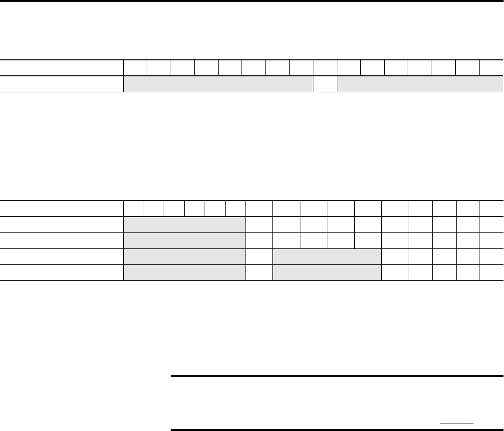
Output Array Word 4 15 14 13 12 11 10 09 08 07 06 05 04 03 02 01 00
Reset Blown Fuse
Not used RBF Not used
Output Array Words 5 to 8 15 14 13 12 11 10 09 08 07 06 05 04 03 02 01 00
Counter 0 Control Bits (Word 5)
Not used RPW RREZ Z Inh Z Inv D Inh D Inv RU RO SP En
Counter 1 Control Bits (Word 6)
Not used RPW RREZ Z Inh Z Inv D Inh D Inv RU RO SP En
Counter 2 Control Bits (Word 7)
Not used RPW Not used D Inv RU RO SP En
Counter 3 Control Bits (Word 8)
Not used RPW Not used D Inv RU RO SP En
TIP
The order of precedence for the Preset and Direct Write actions is as
follows:
1. Preset
2. Direct Write
IMPORTANT
Setting any of the control bits under certain conditions of the
NumberOfCounters value will result in the input error flag,
Ctr[n].InvalidCounter. For more information, see IC - Invalid Counter
(Ctr[1].InvalidCounter to Ctr[3].Invalid Counter) table on page 107.