Installation Instructions Compact I/O High-speed Counter Module Catalog Number 1769-HSC Topic Page Important User Information 2 Environment and Enclosure 3 North American Hazardous Location Approval 4 Module Features 5 Hardware Description 6 Module Installation 7 System Planning 8 System Assembly 8 System Mounting 10 Replace the Module within a System 12 Field Wiring Connections 13 Output Operation 20 Module Powerup 22 Temperature Derating 23 Specifications 26 Additional Res
Compact I/O High-speed Counter Module Important User Information Solid-state equipment has operational characteristics differing from those of electromechanical equipment. Safety Guidelines for the Application, Installation and Maintenance of Solid State Controls (Publication SGI-1.1 available from your local Rockwell Automation sales office or online at http://www.rockwellautomation.
Compact I/O High-speed Counter Module 3 Environment and Enclosure ATTENTION: This equipment is intended for use in a Pollution Degree 2 industrial environment, in overvoltage Category II applications (as defined in IEC publication 60664-1), at altitudes up to 2000 m (6562 ft) without derating. This equipment is considered Group 1, Class A industrial equipment according to IEC/CISPR 11.
Compact I/O High-speed Counter Module North American Hazardous Location Approval The following information applies when operating this equipment in hazardous locations. Informations sur l’utilisation de cet équipement en environnements dangereux. Products marked "CL I, DIV 2, GP A, B, C, D" are suitable for use in Class I Division 2 Groups A, B, C, D, Hazardous Locations and nonhazardous locations only.
Compact I/O High-speed Counter Module 5 Module Features The 1769-HSC module is a 1 MHz counter/encoder input module with 4 onboard 5…30V DC sourcing outputs designed for high-speed control applications, such as flow control, measuring length, position, speed, frequency, or duration.
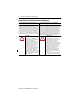
Compact I/O High-speed Counter Module Hardware Description 9a 1 0 1 8a 8a 3 2 3 A0 B0 Z0 A1 B1 Z1 IN OUT IN OUT 2a High Speed Counter 0 2 1 3 A0 B0 Z0 A1 B1 Z1 High Speed Counter 6a DANGER Do Not Remove RTB Under Power Unless Area is Non-Hazardous 5a OUT 0 OUT DC +5V/24V 10 OUT 1 OUT 2 OUT DC COM OUT 3 6b A0+ A0- 5 B0+ B0Z0+ Z0A1+ A1B1+ 5b B1Z1+ Z1Ensure Adjacent Bus Lever is Unlatched/Latched Before/After Removing/Inserting Module 4 7 1769-HSC 2b 8b 8b 9b I
Compact I/O High-speed Counter Module 7 Module Installation The 1769-HSC module is suitable for use in an industrial environment when installed in accordance with these instructions. Specifically, this equipment is intended for use in clean, dry environments (Pollution Degree 2(1)) and with circuits not exceeding Over Voltage Category II(2) (IEC 60664-1).(3) Removal and Insertion Under Power (RIUP) WARNING: When you insert or remove the module while backplane power is on, an electrical arc can occur.
Compact I/O High-speed Counter Module System Planning There are several factors to consider when planning your system: • A 1769-ECR (right-end cap) or 1769-ECL (left-end cap) is required to terminate the end of the Compact I/O bus. • Each bank of Compact I/O modules must have its own power supply. (A MicroLogix 1500 base unit acts as the power supply for modules directly connected to it.
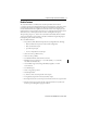
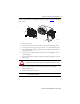
Compact I/O High-speed Counter Module 9 Refer to the illustration when assembling the Compact I/O system. See page 6 for a description of the module. A D E C B G B F 45197 1. Disconnect the power. 2. Check that the bus lever of the module (A) is in the unlocked (fully right) position. 3. Use the upper and lower tongue-and-groove slots (B) to secure the modules together. 4. Move the module back along the tongue-and-groove slots until the bus connectors (C) line up with each other. 5.
Compact I/O High-speed Counter Module System Mounting ATTENTION: This product is intended to be mounted to a well-grounded mounting surface, such as a metal panel. Additional grounding connections from the power supply's mounting tabs or DIN rail (if used) are not required unless the mounting surface cannot be grounded. Refer to Industrial Automation Wiring and Grounding Guidelines, publication 1770-4.1, for additional information.
Compact I/O High-speed Counter Module 11 Figure 2 - Compact I/O Modules with MicroLogix 1500 Base Unit and Processor DIN Rail Center Line 13.5 mm (0.53 in.) 132 mm (5.19 in.) 28.5 mm (1.12 in.) 147.4 mm (5.81 in.) (1.38 in.) 35 mm (1.38 in.) 118 mm (4.65 in) 59 mm (2.32 in.) 59 mm (2.32 in.) 122.6 mm (4.83 in.) 35 mm 168 mm (6.62 in.) 147 mm (5.79 in.) Mounting Hole Dimension 14.7 mm (0.58 in.) Important: Hole spacing tolerance: ±0.04 mm (0.016 in.).
Compact I/O High-speed Counter Module DIN Rail Mounting The module can be mounted on the following DIN rails: • EN 50 022 - 35 x 7.5 mm (1.38 x 0.3 in.) • EN 50 022 - 35 x 15 mm (1.38 x 0.59 in.) ATTENTION: During panel or DIN-rail mounting of all devices, be sure that all debris (metal chips, wire strands, and so forth) is kept from falling into the module. Debris that falls into the module could cause damage on powerup. 1. Before mounting the controller on a DIN rail, close the DIN rail latches. 2.
Compact I/O High-speed Counter Module 13 If you feel excessive resistance, make sure that you disconnected the module from the bus and that you removed both mounting screws (or opened the DIN latches). TIP It may be necessary to rock the module slightly from front to back to remove it, or, in a panel-mounted system, to loosen the screws of adjacent modules. 6. Before installing the replacement module, be sure that the bus lever on the right-side adjacent module is in the unlocked (fully right) position.
Compact I/O High-speed Counter Module Grounding Guidelines • This product is intended to be mounted to a well-grounded mounting surface, such as a metal panel. Additional grounding connections from the module’s mounting tabs or DIN rail (if used) are required only when the mounting surface is non-conductive and cannot be grounded. • Keep shield connection to ground as short as possible. • Ground the shield drain wire at the 1769-HSC module’s input end only.
Compact I/O High-speed Counter Module 15 Figure 5 - Single-Ended Encoder Wiring Cable(1) VS +VDC GND COM R Power Supply (2) A1(+) A A1(–) B Allen-Bradley 845H Series Single-ended Encoder B1(+) B1(–) Z1(+) Z Z1(–) Shield Shield/Housing Connect only if housing is electronically isolated from the motor and ground. Earth Module Inputs (1) Refer to your encoder manual for proper cable type.
Compact I/O High-speed Counter Module Figure 6 - Discrete Device Wiring +VDC COM Power Supply Proximity Sensor VS A1(+) OUT A1(–) COM VS Solid-state Switch OUT B1(+) COM B1(–) VS OUT R (1) Z1(+) COM Z1(–) Photo-electric Sensor with Open Collector Sinking Output Module Inputs (1) External resistors are required if they are not internal to the sensor. The pull-up resistor (R) value depends on the power supply value.
Compact I/O High-speed Counter Module 17 Output Wiring Basic wiring(1) of output devices(2) to the module is shown in Figure 7. ATTENTION: Follow these guidelines: • Miswiring of the module to an AC power source or applying reverse polarity will damage the module. • Be careful when stripping wires. Wire fragments that fall into a module could cause damage at powerup. Once wiring is complete, be sure that the module is free of all metal fragments.
Compact I/O High-speed Counter Module Wire the Finger-safe Terminal Block When wiring the terminal block, keep the finger-safe cover in place. Wiring the Finger-safe Terminal Block Upper Retaining Screw Lower Retaining Screw 1. Loosen the terminal screws to be wired. 2. Route the wire under the terminal pressure plate. You can use the bare wire or a spade lug. The terminals accept a 6.35 mm (0.25 in.) spade lug. TIP The terminal screws are non-captive. Therefore, it’s possible to use a ring lug (6.
Compact I/O High-speed Counter Module 19 Wire the Modules After the module is properly installed, wire the modules by using this procedure. To provide proper operation and high immunity to electrical noise, always use shielded wire. ATTENTION: To prevent shock hazard, care should be taken when wiring the module to signal sources. Before wiring any module, disconnect power from the system power supply and from any other source to the module. Do not wire more than two conductors on any single terminal.
Compact I/O High-speed Counter Module Output Operation The four output terminals must be powered by a user-supplied external source. User-power range is from 5…30V DC. See Output Specifications on page 27 for voltage and current levels. There is no isolation between the outputs, but the outputs are isolated from the inputs and the 1769 Compact bus.
Compact I/O High-speed Counter Module 21 Transistor Output Transient Pulses The maximum duration of the transient pulse occurs when minimum load is connected to the output. However, for most applications, the energy of the transient pulse is not sufficient to energize the load. ATTENTION: A transient pulse occurs in transistor outputs when the external DC supply voltage is applied to the output common terminals (for example, via the master control relay).
Compact I/O High-speed Counter Module IN At module powerup, a series of internal diagnostic tests are performed. These diagnostic tests must be successfully completed or the module OK status indicator remains off or red, and a module error is reported to the controller.
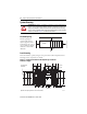
Compact I/O High-speed Counter Module 23 Temperature Derating The following graphs indicate how much current can be drawn from the power supply at the indicated case temperature without damaging it. Maximum Input Voltage - 24V DC Operation Voltage Derating Based on Temperature Volts (DC) 26.4V DC at 55 °C (131 °F) (-32) (50) (68) (86) (104) Ambient Temperature, °C (°F) (122) (158) 45204 Temperature Derated Voltage(1) 0…40 °C (-32…104 °F) 30V DC 55 °C (131 °F) 26.
Compact I/O High-speed Counter Module Maximum Output Current per Point - 5V DC Operation Current per Point (A) Current Derating Based on Temperature 0.5 A at 60 °C (140 °F) (-32) (50) (68) (86) (104) (122) (140) (158) Ambient Temperature, °C (°F) 45206 Temperature Derated Current 0…40 °C (-32…104 °F) 1A 60 °C (140 °F) 0.
Compact I/O High-speed Counter Module 25 Maximum Output Current per Point - 24V DC Operation Current per Point (A) Current Derating Based on Temperature 0.25 A at 60 °C (140 °F) (-32) (50) (68) (86) (104) (122) (140) (158) Ambient Temperature, °C (°F) 45208 Temperature Derated Current 0…40 °C (-32…104 °F) 1A 55 °C (131°F) 0.5 A 60 °C (140°F) 0.
Compact I/O High-speed Counter Module Specifications Technical Specifications - 1769-HSC Attribute 1769-HSC Dimensions (H x W x D), approx. 118 x 35 x 87 mm (4.65 x 1.38 x 3.43 in.) Height including mounting tabs is 138 mm (5.43 in.) Shipping weight (with carton), approx. 309 g (0.681 lb) Bus current draw, max 425 mA at 5V DC 0 mA at 24V DC Heat dissipation 6.
Compact I/O High-speed Counter Module 27 Input Specifications - 1769-HSC Attribute 1769-HSC On-state voltage, min 2.6V DC On-state current, min 6.8 mA Off-state voltage, max 1.0V DC Off-state current, max 1.5 mA Off-state leakage current, max 1.5 mA Input current, max 15 mA Input current, min 6.
Compact I/O High-speed Counter Module Environmental Specifications - 1769-HSC Attribute 1769-HSC Temperature, operating 0…60 °C (32…140 °F) IEC 60068-2-1 (Test Ad, Operating Cold), IEC 60068-2-2 (Test Bd, Operating Dry Heat), IEC 60068-2-14 (Test Nb, Operating Thermal Shock) Temperature, surrounding air, max 40 °C (104 °F) Temperature, nonoperating -40…85 °C (-40…185 °F) IEC 60068-2-1 (Test Ab, Unpackaged Nonoperating Cold), IEC 60068-2-2 (Test Bb, Unpackaged Nonoperating Dry Heat), IEC 60068-2
Compact I/O High-speed Counter Module 29 Environmental Specifications - 1769-HSC Attribute 1769-HSC EFT/B immunity ±2 kV at 5 kHz on power ports ±2 kV at 5 kHz on signal ports IEC 61000-4-4 Surge transient immunity IEC 61000-4-5 Conducted RF immunity ±1 kV line-line (DM) and ±2 kV line-earth (CM) on power ports ±1 kV line-line (DM) and ±2 kV line-earth (CM) on signal ports ±1 kV line-earth (CM) on shielded ports 10V rms with 1 kHz sine-wave 80% AM from 150 kHz…80 MHz IEC 61000-4-6 (1) This rating
Compact I/O High-speed Counter Module Additional Resources These documents contain additional information concerning related Rockwell Automation products. Resource Description Compact High-speed Counter Module User Manual, publication 1769-UM006 Detailed description of how to use your High-speed Counter Module. ControlLogix System User Manual, publication 1756-UM001 Detailed description of how to use your ControlLogix operating system.
Compact I/O High-speed Counter Module 31 Notes: Publication 1769-IN030B-EN-P - October 2010
Rockwell Automation Support Rockwell Automation provides technical information on the Web to assist you in using its products. At http://www.rockwellautomation.com/support/, you can find technical manuals, a knowledge base of FAQs, technical and application notes, sample code and links to software service packs, and a MySupport feature that you can customize to make the best use of these tools.