Installation Instructions Compact 32-point Solid-state 24V dc Source Output Module Catalog Number 1769-OB32 Use this document as a guide when installing a Compact™ 32-point solid-state 24V dc source output module.
Compact 32-point Solid-state 24V dc Source Output Module Important User Information Because of the variety of uses for the products described in this publication, those responsible for the application and use of these products must satisfy themselves that all necessary steps have been taken to assure that each application and use meets all performance and safety requirements, including any applicable laws, regulations, codes and standards.
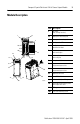
Compact 32-point Solid-state 24V dc Source Output Module 3 Module Description Item Description 2a 1 3 WARNING -Do Not Remove RTB Unless Area is Non-Hazardous 10a OUT 0 OUT 2 OUT 4 OUT 6 OUT 8 10 10b OUT 10 OUT 12 +VDC 1 OUT 1 OUT 3 OUT 5 OUT 7 OUT 9 OUT 16 OUT 18 OUT 20 OUT 22 OUT 24 OUT 26 OUT 11 1 bus lever (with locking function) 2a upper panel mounting tab 2b lower panel mounting tab 3 I/O diagnostic LEDs 4 module door with terminal identification label 5a movable bus connector
Compact 32-point Solid-state 24V dc Source Output Module Module Installation Compact I/O is suitable for use in an industrial environment when installed in accordance with these instructions. Specifically, this equipment is intended for use in clean, dry environments (Pollution degree 2(1)) and to circuits not exceeding Over Voltage Category II(2) (IEC 60664-1).
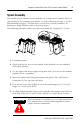
Compact 32-point Solid-state 24V dc Source Output Module 5 System Assembly The module can be attached to the controller or an adjacent I/O module before or after mounting. For mounting instructions, see Panel Mounting on page 6, or DIN Rail Mounting on page 8. To work with a system that is already mounted, see Replacing a Single Module within a System on page 8. The following procedure shows you how to assemble the Compact I/O system. 3 4 2 1 6 1 5 30536-M 1. Disconnect power. 2.
Compact 32-point Solid-state 24V dc Source Output Module 7. Attach an end cap terminator (5) to the last module in the system by using the tongue-and-groove slots as before. 8. Lock the end cap bus terminator (6). IMPORTANT A 1769-ECR or 1769-ECL right or left end cap must be used to terminate the end of the serial communication bus. Mounting Expansion I/O ATTENTION ! During panel or DIN rail mounting of all devices, be sure that all debris (metal chips, wire strands, etc.
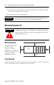
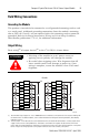
Compact 32-point Solid-state 24V dc Source Output Module 7 Panel Mounting Using the Dimensional Template Host Controller Spacing for single-wide modules 35 mm (1.378 in.) Spacing for one-and-a half-wide modules 52.5 mm (2.067 in.) Refer to host controller documentation for this dimension. Note: Overall hole spacing tolerance: ±0.4 mm (0.016 in.). Locate holes every 17.5 mm (0.689 in.) to allow for a mix of single-wide and one-and-a-half-wide modules (e.g. 1769-OA16).
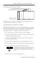
Compact 32-point Solid-state 24V dc Source Output Module DIN Rail Mounting The module can be mounted using these DIN rails: 35 x 7.5 mm (EN 50 022 - 35 x 7.5) or 35 x 15 mm (EN 50 022 - 35 x 15). Before mounting the module on a DIN rail, close the DIN rail latches. Press the DIN rail mounting area of the module against the DIN rail. The latches will momentarily open and lock into place.
Compact 32-point Solid-state 24V dc Source Output Module 9 Field Wiring Connections Grounding the Module This product is intended to be mounted to a well-grounded mounting surface such as a metal panel. Additional grounding connections from the module’s mounting tabs or DIN rail (if used), are not required unless the mounting surface cannot be grounded. Refer to Industrial Automation Wiring and Grounding Guidelines, Allen-Bradley publication 1770-4.1, for additional information.
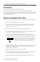
Compact 32-point Solid-state 24V dc Source Output Module A removable write-on label is included with the module. Remove the label from the door, mark the identification of each terminal with permanent ink, and slide the label back into the door. Your markings (ID tag) will be visible when the module door is closed. R SLOT# MODULE TYPE L 30517-M Removing the Finger-safe Terminal Block When wiring field devices to the module, it is not necessary to remove the terminal block.
Compact 32-point Solid-state 24V dc Source Output Module 11 2. Route the wire under the terminal pressure plate. You can use the bare wire or a spade lug. The terminals will accept a 6.35 mm (0.25 in.) spade lug. TIP The terminal screws are non-captive. Therefore, it is possible to use a ring lug [maximum 1/4 inch o.d. with a 0.139 inch minimum i.d. (M3.5)} with the module. 3. Tighten the terminal screw making sure the pressure plate secures the wire.
Compact 32-point Solid-state 24V dc Source Output Module Wire Size and Terminal Screw Torque Each terminal accepts as many as two wires with these restrictions: Wire Type Wire Size Terminal Screw Torque Retaining Screw Torque Solid Cu-90°C (194°F) #14 to #22 AWG 0.68 Nm (6 in-lbs) 0.46 Nm (4.1 in-lbs) Stranded Cu-90°C (194°F) #16 to #22 AWG 0.68 Nm (6 in-lbs) 0.46 Nm (4.
Compact 32-point Solid-state 24V dc Source Output Module 13 The output module’s input data file reflects the output data echo of the module, not necessarily the electrical state of the output terminals. It does not reflect shorted or open outputs. IMPORTANT It is important to use this input word if the controller adapter supports the Program Mode or Fault Mode function, and if it is configured to use them.
Compact 32-point Solid-state 24V dc Source Output Module Program State Word Word 1, the program state word, selects the hold last state or user-defined safe state condition for each individual output on a system transition from Run to Program. Condition Bit Setting User-defined Safe State 0 Hold Last State 1 Value Bit Setting Program Value Word The program value word, word 2, is used to program the user-defined safe state value (0=Off, 1=On).
Compact 32-point Solid-state 24V dc Source Output Module 15 Module Default Condition The modules default condition is all zeros, programming the conditions shown.
Compact 32-point Solid-state 24V dc Source Output Module Specifications General Specifications Specification Value Dimensions 118 mm (height) x 87 mm (depth) x 52.5 mm (width) height including mounting tabs is 138 mm 4.65 in. (height) x 3.43 in (depth) x 2.07 in (width) height including mounting tabs is 5.43 in. Approximate Shipping Weight (with carton) 450g (0.992 lbs.
Compact 32-point Solid-state 24V dc Source Output Module 17 Output Specifications Specification 1769-OB32 Voltage Category 24V dc Operating Voltage Range 20.4V dc to 26.4V dc (source(1)) Number of Outputs 32 Bus Current Draw (max.) 300 mA at 5V dc (1.5W) Heat Dissipation 4.5 Total Watts (The Watts per point, plus the minimum Watts, with all points energized.) Signal Delay (max.) – resistive load turn-on = 0.1 ms turn-off = 1.0 ms Off-State Leakage (max.)(2) 1.0 mA at 26.
Compact 32-point Solid-state 24V dc Source Output Module Temperature Derating The area within the curve represents the safe operating range for the module under various conditions of user supplied voltages and ambient temperatures. Temperature Derating 1769-OB32 Maximum Amperes per Common vs. Temperature Maximum Amperes Per Common 8.00 7.50 7.00 6.50 6.00 5.50 5.00 4.50 4.
Compact 32-point Solid-state 24V dc Source Output Module 19 Temperature Derating Maximum Amperes Per Point 1769-OB32 Maximum Amperes per Point vs. Temperature 1.00 0.95 0.90 0.85 0.80 0.75 0.70 0.65 0.60 0.55 0.50 30˚C (86˚F) 40˚C (104˚F) 50˚C (122˚F) Ambient Termperature 60˚C (140˚F) 30526-M Transistor Output Transient Pulses The maximum duration of the transient pulse occurs when minimum load is connected to the output.
Compact 32-point Solid-state 24V dc Source Output Module The graph below illustrates that the duration of the transient is proportional to the load current. Therefore, as the on-state load current increases, the transient pulse decreases. Power-up transients do not exceed the time duration shown below, for the amount of loading indicated, at 60°C (140°F). Transient Pluse Duration as a Function of Load Current 1.0 0.9 Time-Duration of transient (mS) 0.8 0.7 0.6 0.5 0.4 0.3 0.2 0.1 0.
Compact 32-point Solid-state 24V dc Source Output Module 21 Hazardous Location Considerations This equipment is suitable for use in Class I, Division 2, Groups A, B, C, D or non-hazardous locations only. The following WARNING statement applies to use in hazardous locations. WARNING ! EXPLOSION HAZARD • Substitution of components may impair suitability for Class I, Division 2. • Do not replace components or disconnect equipment unless power has been switched off or the area is known to be non-hazardous.
Compact 32-point Solid-state 24V dc Source Output Module For More Information For Refer to this Document Pub. No. A more detailed description of how to install MicroLogix 1200 & 1500 and use your Compact™ I/O with Programmable Controllers User MicroLogix™ 1200 & 1500 programmable Manual controller. 1764-UM001B-US-P A more detailed description of how to install 1769-ADN DeviceNet Adapter User and use your Compact I/O with the Manual 1769-ADN DeviceNet Adapter.
Compact 32-point Solid-state 24V dc Source Output Module 23 Notes: Publication 1769-IN031A-EN-P - April 2003
Compact, MicroLogix, CompactLogix, RSLogix 500, and RSNetWorx for DeviceNet are trademarks of Rockwell Automation. DeviceNet is a trademark of Open DeviceNet Vendor Association (ODVA). Publication 1769-IN031A-EN-P - April 2003 PN 40071-153-01(1) © 2003 Rockwell International Corporation. Printed in the U.S.A.