
Owner manual


Appendix
A
A-1
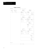
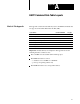
HART Command Data Table Layouts
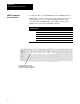
This appendix contains the data table layouts for the HART commands that
are supported in the Smart Transmitter Toolkit (STT).
If you want to: Use Hart Command: See page:
Read HART Address
0 A2
Read Primary Variable 1 A4
Read Dynamic Variables & Primary Variable Current 3 A6
Write Primary Variable Range Values 35 A8
Reset Configuration Change Flag 38 A10
Set Primary Variable Zero 43 A12
Write Primary Variable Units 44 A14
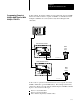
Important: All data table layout examples in this appendix are shown
assuming that these conditions exist:
The 1770-HT1 is located at I/O rack 4 and I/O group 6.
The HART field device is wired:
-to channel 3 of a 1770-HT8 or 1770-HT16
-point-to-point (polling address is 0)
The HART field device uses a long-frame address.
What's In This Appendix