DH 485 Communication Interface (Cat. No.
Important User Information Because of the variety of uses for this product and because of the differences between solid state products and electromechanical products, those responsible for applying and using this product must satisfy themselves as to the acceptability of each application and use of this product. For more information, refer to publication SGI-1.1 (Safety Guidelines For The Application, Installation And Maintenance of Solid State Control).
Table of Contents Manual Overview . . . . . . . . . . . . . . . . . . . . . . . . . . . . . . . . P 1 Audience . . . . . . . . . . . . . . . . . . . . . . . . . . . . . . . . . . . . . . . . . . Related Publications . . . . . . . . . . . . . . . . . . . . . . . . . . . . . . . . . . Publication Number . . . . . . . . . . . . . . . . . . . . . . . . . . . . . . . . Related Products . . . . . . . . . . . . . . . . . . . . . . . . . . . . . . . . . . . . Product Catalog Number . . . . . . . . . . . . . . .
ii Table of Contents Specifications . . . . . . . . . . . . . . . . . . . . . . . . . . . . . . . . . . A 1 RS 232C Interface . . . . . . . . . . . . . . . . . . . . . . . . . . . . . . . . . . . DH 485 Interface . . . . . . . . . . . . . . . . . . . . . . . . . . . . . . . . . . . . Electrical . . . . . . . . . . . . . . . . . . . . . . . . . . . . . . . . . . . . . . . . . . Physical . . . . . . . . . . . . . . . . . . . . . . . . . . . . . . . . . . . . . . . . . . Environmental . . . . . . . . . . .
Preface Manual Overview This manual: describes the features and capabilities of the 1770-KF3 tells you how to install, configure, and operate your 1770-KF3 gives troubleshooting tips on diagnosing problems defines the specifications of the 1770-KF3 Audience Read this manual if you are installing and configuring a 1770-KF3 Interface Module for use with a DH-485 network.
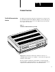
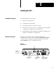
Chapter 1 Product Overview The DH 485 Communication Interface The DH-485 Communication Interface module links host computers with the Allen-Bradley RS-485 Data Highway (DH-485). The module supports the protocol required to act as a node on the DH-485 network, freeing the host computer from this task. Figure 1.1 The DH 485 Communication Interface (1770 KF3) Important: The DH-485 Communication Interface module (cat. no.
Chapter 1 Product Overview The DH 485 Network The DH-485 communication network allows devices on the plant floor to share information.
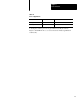
Chapter 1 Product Overview Table 1.A Protocol Applications Protocol Point to Point Multi Point Full duplex Yes No Half duplex Yes No A description of these protocols is given in the Data Highway/Data Highway Plus/DH-485 Protocol and Command Set Manual (publication 1770-6.5.16).
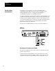
Chapter 2 Installing the KF3 Installation Procedures Interface Connections To install the KF3, follow these steps: 1. Define your network needs. 2. Construct the necessary cables. 3. Ground and terminate your network correctly. 4. Determine the correct voltage for your application and set the KF3’s voltage selector. Change power cord if necessary. 5. Check the KF3’s default configuration parameters and change those which are not suitable for your application. Figure 2.
Chapter 2 Installing the KF3 DH 485 Cabling Considerations Depending on your application, you can use the KF3 module to communicate with a single station via a point-to-point link, or with multiple DH-485 stations (for example, the SLC 500 family of programmable controllers), via the DH-485 network. You must construct the necessary cable or cables for each application. Use a jacketed and shielded cable with two twisted wire pairs and a drain wire.
Chapter 2 Installing the KF3 Table 2.A Wire/Terminal Connections for Imtermediate Nodes For this Wire/Pair Connect this Wire To this Terminal Shield/Drain Non jacketed Terminal 2 - Shield Black/White Black Wire Cut back - No connection White Wire Terminal 3 (Signal Ground) Black Wire Terminal 4 (Data A) Red Wire Terminal 5 (Data B) Black/Red The nodes at each end of the network must be terminated. Install a jumper wire between terminals 5 and 6 to enable the impedance built into the module.
Chapter 2 Installing the KF3 Connecting via a DH 485 Link (Point to Point Configuration) Figure 2.4 shows a point-to-point link consisting of a single SLC 500 programmable controller and one host computer station. Figure 2.4 A Point to Point DH 485 Link RS 232C Cable DH 485 Cable Belden #9842 Link Coupler 1747 AIC Host Computer SLC 500 Controller KF3 1747 C11 Cable This configuration requires a KF3 and one link coupler. The SLC 500 controller is connected to the link coupler with a 1747-C11 cable.
Chapter 2 Installing the KF3 Connecting to a DH 485 Network (Multi Point Configuration) Figure 2.6 shows a network consisting of three SLC 500 programmable controllers and one host computer station. Figure 2.
Chapter 2 Installing the KF3 Figure 2.7 Connection for First Segment of a Multidrop Network Jumper to ground shield connector DH 485 Cable Jumper to terminate node 1770 KF3 on one end of the link Link coupler to first SLC 500 * The black wire of the white/black pair should be cut back (no connection). The cable connecting the second and third nodes of the multidrop network (neither of which is an end station) is shown in Figure 2.8. Figure 2.
Chapter 2 Installing the KF3 Figure 2.9 Connection for Last Segment of a Multidrop Network DH 485 Cable Jumper to terminate node Third node Fourth node on the end of the multidrop network * The black wire of the white/black pair should be cut back (no connection). Installing the DH 485 Cable The DH-485 cable consists of a number of daisy-chained segments. The total length of the combined segments must not exceed 4,000 feet.
Chapter 2 Installing the KF3 RS 232C Cabling Considerations Cabling for the RS-232C connector of the KF3 will vary depending on your application. The pinouts for this connector are given in Table 2.B. Table 2.B RS 232C Connector Pinouts Signal Abbreviation Direction Pin No. Meaning Chassis Ground - - 1 The cable shield must be connected to chassis ground at one end only. Transmit Data TXD Output 2 RS 232C serialized data output from the module.
Chapter 2 Installing the KF3 Use Belden #8723 (or equivalent) cable to construct a cable to connect the KF3 to a computer. Important: The length must not exceed 50 feet, and the cable shield must be connected to chassis ground (using Pin 1) at the KF3 end only. There are various cabling options depending on whether or not your application makes use of handshake signals, whether or not you are connecting to a 9-pin serial port for an IBM AT, and whether or not your computer uses standard IBM pinouts.
Chapter 2 Installing the KF3 If your computer requires active DSR and CTS signals, add jumpers to the computer connections as shown in Figures 2.13 and 2.14. Figure 2.13 Jumper Positions for DSR and CTS Lines (25 pin) KF3 Computer 1 Shield TXD 2 3 RXD RXD 3 2 TXD GND 7 7 GND 4 RTS 5 CTS 6 DSR 8 DCD 20 DTR Figure 2.
Chapter 2 Installing the KF3 If you are using handshake signals with your computer, use the connection shown in Figure 2.15 or 2.16. Figure 2.15 Connection to IBM Computer with Handshake Signals (25 pin) KF3 Computer 1 Shield TXD 2 3 RXD RXD 3 2 TXD RTS 4 5 CTS CTS 5 4 RTS GND 7 7 GND DSR 6 20 DTR DCD 8 6 DSR DTR 20 8 DCD Figure 2.
Chapter 2 Installing the KF3 Modem Cabling Considerations The KF3 is connected to a modem via a direct 25-pin-to-25-pin cable, which you must construct using Belden #8723 (or equivalent) cable. Important: The length must not exceed 50 feet, and the cable shield must be connected to chassis ground (using Pin 1) at the KF3 end only. Figure 2.
Chapter 2 Installing the KF3 Auto-Answer: These modems have self-contained timeouts and tests, and can answer and hang up the phone automatically. The module has no means of controlling an auto-dial modem, but it can be used in conjunction with a separate auto-dialer. Voltage Selection CAUTION: The KF3 must be set to the correct voltage before it is powered up. Connecting to 115V power with the switch set to 230V will result in erratic operation.
Chapter 2 Installing the KF3 230V Operation Set the power select switch to “230V” as shown in Figure 2.19. Figure 2.19 Power Select Switch Set for 230V Operation FUSES: 0.1A 250V TYPE 5mm X 20MM Slide to left for 230V operation CAUTION: FOR CONTINUED PROTECTION AGAINST RISK OF FIRE REPLACE ONLY WITH THE SAME TYPE AND RATING OF FUSE. CAUTION: DOUBLE FOLD NEUTRAL FUSES ËËË CAUTION: The power cord supplied is approved for 115V operation only.
Chapter 2 Installing the KF3 Figure 2.20 Replacing Fuses Fuse Holder Cap Fuse Fuse Holder Assembly Fuse Receptacle Positioning the KF3 Screwdriver The KF3 is intended to sit on a flat surface, such as a desk top or shelf. It has been designed for operation in both control room and plant floor environments. Where you place the KF3 is determined largely by the 50-foot RS-232 cable length restrictions, and by access to an AC power outlet.
Chapter 3 Configuring the KF3 Configuration You configure the KF3’s communication parameters using the push buttons and displays located on the bottom of the module. The module saves them in nonvolatile memory. Factory default settings (shown in Table 3.B) should be adequate for most industrial usages. Important: Verify that all parameter settings are correct for your purposes before connecting the KF3 to your network. The KF3 has two modes of operation, run mode and configuration mode.
Chapter 3 Configuring the KF3 Displays Figure 3.1 shows the configuration displays on the bottom of the module. The left display (one digit) shows the number of the communication parameter being configured. The right display (two digits) shows the current setting for that parameter. Communication parameters are configured in two menus, a main menu, for basic parameters, and a submenu, for more advanced parameters. Push Buttons Figure 3.1 shows three push buttons labelled View, Data, and Exit.
Chapter 3 Configuring the KF3 Configuration Steps Entering Configuration Mode 1. Press the View button to enter configuration mode. The first parameter number will be displayed on the left, with its current setting on the right. The KF3 continues to communicate while in configuration mode. Changes in configuration do not affect operation until they are saved and the module returns to run mode. Configuring 2.
Chapter 3 Configuring the KF3 Figure 3.2 Successful Save Display If the save is not successful, your KF3 is malfunctioning. The left display will show hardware fault number 6 (see Table 5.B) and the front panel fault indicator will light. If this happens, contact your A-B representative. Exit Without Saving 6. Pressing only the Exit button while in the main menu takes the module out of configuration mode and into run mode without saving any changes. The previous settings will remain in effect.
Chapter 3 Configuring the KF3 Basic Communication Parameters For normal operation, the basic communication parameters must be configured. For special communication needs, configure the advanced communication parameters, which permit more flexibility in tuning the operation of the module. Important: The KF3 is shipped from the factory with the DH-485 Node Address set to 00.
Chapter 3 Configuring the KF3 Table 3.B Basic Configuration Parameters (continued) Parameter Number Parameter Description Factory Default RS 232C Baud Rate Baud rate of the RS 232C link between the host computer and the KF3. The host computer and KF3 must be set to the same baud rate. 9600 baud (96). RS 232C Parameters Possible rates are 300 (03), 600 (06), 1200 (12), 2400 (24), 4800 (48), 9600 (96), 19200 (19). RS 232C Parity Parity of the characters on the RS 232C link.
Chapter 3 Configuring the KF3 Advanced Communication Parameters The advanced communication parameters are located in the Submenu. When parameter 9, the Submenu entry parameter, is shown on the left display, the Data display on the right will show dashes. Press the Data button to enter the Submenu and display the submenu parameter numbers. The number on the left will change from 9 to 0, and its decimal point will light up, remaining lit as long as you are in the Submenu. Figure 3.
Chapter 3 Configuring the KF3 Table 3.C Submenu Configuration Parameters Parameter Number Parameter Description Factory Default Maximum Token Holder The node address of the highest numbered master station on the Address DH 485 link. The valid range for Maximum Token Holder is 01 31. (31). If all stations have consecutive addresses, this parameter should be set to the address of the highest numbered master station on the link.
Chapter 3 Configuring the KF3 Table 3.C Submenu Configuration Parameters Parameter Number Parameter Description Factory Default CTS to Transmit Delay The delay between the CTS signal and the start of transmission by the KF3 (half duplex only). The delay is from 0 seconds to 0.99 seconds, in 10 ms (0.01 second) increments. To calculate the delay, multiply the number in the display by 0.01 seconds. No delay (00). For example: A setting of 48 means 48 x 0.01 = 0.48 seconds.
Chapter 3 Configuring the KF3 Verifying Your Configuration Parameters Before connecting the KF3 to your network, cycle through the parameter settings. If you have properly defined your network needs, you know what parameter settings your network requires. Compare the parameters you need for your network to the settings in the module. If you have made no changes to the default settings, the values shown in parentheses in the Factory Default column of the Tables 3.B and 3.C should appear in the displays.
Chapter 4 Communicating with the KF3 Read this chapter if you are configuring a half-duplex network or if you plan to write a communication driver. A thorough understanding of DF1 protocol, PLC command sets and the use of slave devices on the DH-485 communication network is required. DF1 Communication The KF3 supports full-duplex DF1 protocol and half-duplex DF1 slave protocol on its RS-232C connection to a host computer.
Chapter 4 Communicating with the KF3 Half Duplex DF1 Protocol Local Mode Local mode requires an intelligent master device, capable of specifying both a station address and a destination address. Because the KF3 acts as a slave on a DF1 half-duplex network, the half-duplex master’s access to the DH-485 nodes is indirect: i.e., the destination address and the station address are generally different.
Chapter 4 Communicating with the KF3 Half Duplex DF1 Protocol Remote Mode The valid range of slave addresses on a half-duplex network is 000-376 octal – a total of 255 stations. The valid range of addresses on a DH-485 network is 00-31 decimal. In order to make these two systems compatible, two special submenu configuration options have been included in the KF3 (see Table 3.C). The first, submenu option 6, must be set to the address of the half-duplex master.
Chapter 4 Communicating with the KF3 Table 4.
Chapter 4 Communicating with the KF3 Example: Remote Mode Addressing on a Multidrop Network This example uses the 1771-KGM as the half-duplex master in a multidrop configuration. Each of the KF3s is set to half-duplex remote mode, and has the half-duplex Master Address set to the address of the 1771-KGM (010). Figure 4.
Chapter 4 Communicating with the KF3 The group number is used by the KF3 to create a unique half-duplex DF1 address for each node on the DH-485 networks. The nodes’ addresses would be as follows: Table 4.
Chapter 4 Communicating with the KF3 Slave Packet Formats To invoke DH-485 link layer services, a special PCCC CMD byte is used to support the addition of link-specific information to the packet. Setting the CMD byte = 09 indicates that the packet contains extended link information. When the CMD byte = 09, the packet contains a “Link Type” field (one byte), a “Link Status” field (one byte), and information specific to the link-type command being sent. Figure 4.3 shows the SRD request packet format.
Chapter 4 Communicating with the KF3 03 NAK, Bad LSAP (SRD reply). This link error is returned when the KF3 receives a NAK, Bad LSAP message from the destination station in response to an SRD request. This indicates that the LSAP you are trying to send the SRD request to is invalid for that destination device. 04 NAK, Unimplemented Function (SRD reply). This link error is returned when the KF3 receives a NAK, Unimplemented Function message from the destination station in response to an SRD request.
Chapter 4 Communicating with the KF3 Reply Format, SRD Request The format of a reply to an SRD request is shown in Figure 4.5: the CMD byte will have the reply bit set the link type will be set to SRD Request the link status will indicate success or failure the LSAP of the slave device (SLSAP) will be included if the request was successful, the data will be included. Note that some devices may not return data. The format of data is completely dependent on how the destination device was implemented.
Chapter 4 Communicating with the KF3 This handshaking is necessary to guarantee access to the phone line. If the handshaking protocol is defeated by improper selection of modem options or by jumpers at the connectors, the modem may still answer a call. But if the connection is lost, the modem will not hang up. It will then be impossible for the remote node to reestablish the connection because it will get a busy signal.
Chapter 5 Troubleshooting the KF3 Interpreting the Front Panel LEDs There are four LEDs on the front panel of the KF3. These indicators can help you in diagnosing problems with the module’s installation and operation. Table 5.A LED Indicators LED Indicator Description Power This indicator is lit (green) when the module is plugged in and turned on. Fault This indicator goes on solid red if a hardware fault is detected on power up, or during operation.
Chapter 5 Troubleshooting the KF3 Interpreting the Numeric Displays The numeric displays are used to indicate hardware fault conditions. When the front panel fault indicator is lit, the left display will show a number indicating the type of hardware fault. Table 5.B gives a description of the faults. Table 5.B Hardware Faults This number: Indicates this fault: Processor Fault. A hardware fault was detected in the processor. This is a major fault requiring the module to be returned for servicing.
Chapter 5 Troubleshooting the KF3 Once you initiate active communication on the DF1 link, the RS-232 Activity LED will light up. If this fails to happen, check your RS-232C parameters (Table 3.B, Parameters 3-8). If you are unable to save new configurations successfully, the left display will display hardware fault 6, and the Fault LED on the front will light up. This indicates a malfunction in the module. Contact your A-B representative.
Appendix A Specifications RS 232C Interface Start bits 1 Data bits 8 Parity None, Even Stop bits 1 Baud rates 300, 600, 1200, 2400, 4800, 9600, 19200 Connector DB 25P (male) Output RS 232C Start bits 1 Data bits 8 Parity Even Stop bits 1 Baud rates 300, 1200, 2400, 4800, 9600, 19200 KF3 connector 6 pin, Phoenix MSTBA 1.5/6 G AU Cable connector 6 pin, Phoenix MSTB 2.
Appendix A Specifications Physical Dimensions 9.5" (24.1 cm) wide x 7.1" (18.0 cm) long x 2.4" (6.1 cm) high Weight 2 lbs. (.9 kg) approx. Operating temperature 0°C to 60°C (32°F to 165°F) Storage temperature 40°C to 85°C ( 40°F to 210°F) Operating humidity 5% to 95% (noncondensing) Safety requirements UL 1950 Electromagnetic interference FCC Part 15, Subpart J, Class A DOC R.I.R. SEP.
Appendix B Diagnostic Command Support The KF3 will interpret and respond to the following diagnostic commands: Table B.A KF3 Diagnostic Commands Diagnostic Loop Description Command Byte Function Code (hex) Diagnostic Loop 06 00 Diagnostic Read Counters 06 01 Diagnostic Status 06 03 Reset Diagnostic Counters 06 07 Read Link Parameters 06 09 Set Link Parameters 06 0A You can use this command to check the integrity of the transmissions over the communication link.
Appendix B Diagnostic Command Support Diagnostic Read This command reads the diagnostic counters from the KF3. The format of these counters is given below. Note that the address and size fields can have any value (but they must be included). Figure B.3 Diagnostic Read Command Format 1 byte CMD 06 1 byte STS 2 bytes TNS 1 byte FNC 01 2 bytes ADDR 0000 Figure B.
Appendix B Diagnostic Command Support Table B.B contains the diagnostic read reply values for the KF3: Table B.
Appendix B Diagnostic Command Support Example of an Active Node Table A network consists of 5 stations, numbered 0, 3, 4, 5, and 7. The Active Node Table would look like this: Diagnostic Status 0 3 1 FF 2 FF 3 4 4 5 5 7 6 FF 7 0 This command requests a block of status information from a DH-485 device. The reply contains the information in its DATA field. The status information varies from device to device. The KF3’s status block is given below. Figure B.
Appendix B Diagnostic Command Support Table B.C Diagnostic Status Reply for KF3 Byte Description Status Reply (hex) 1 Mode/Status byte 00 (No Modes) 2 Interface/Processor Type FE Bits 0 3: Interface type (E = Extended) Bits 4 7: Processor type (F = Computer) Diagnostic Counter Reset 3 Extended Interface Type 4 Not Used 5 Series/Revision 2C Bits 0 4: 0 = Revision A 1 = Revision B, etc. Bits 5 7: 0 = Series A 1 = Series B, etc.
Appendix B Diagnostic Command Support Read Link Parameters This command reads the link parameters defined for the KF3. Currently there is only one link parameter: Maximum Token Holder Address. This command returns the value for this parameter in the DATA byte. Figure B.9 Read Link Parameters Command Format 1 byte CMD 06 1 byte 2 bytes STS 1 byte TNS FNC 09 2 bytes PARAMETER 0000 1 byte SIZE 01 Figure B.
Index Numbers 115V operation, 2 13 1747 C11 cable, 2 4 1771 KGM, 4 1, 4 5 230V operation, 2 14 A active node table, B 3, B 4 address conversion, 4 4 advanced communication parameters, 3 7 B back panel, 2 1 basic communication parameters, 3 5 baud rates, A 1 buttons, 3 1, 3 2 C cable constructing, 2 2 length, 1 2 configuration display and push buttons, 3 1, 3 2 configuration mode, 3 1 configuring the KF3, 3 1, 3 3 connection between a KF3 and a modem, 2 12 between two intermediate nodes, 2 6 for first s
I–2 Index diagnostic counter reset, B 5 command format, B 5 reply format, B 5 diagnostic loop, B 1 command format, B 1 reply format, B 1 diagnostic read, B 2 command format, B 2 reply format, B 2 reply values, B 3 diagnostic status, B 4 command format, B 4 reply, B 5 reply format, B 4 dimensions, A 2 displays, 3 1 DSR, 2 8, 4 9 DTR, 2 8, 4 9 duplicate message, 3 6 group number, 3 9 group numbers, 4 3 H half duplex, 1 2, 4 1 master, 4 2, 4 3 half duplex DF1, 3 9 half duplex master, station address, 3 9 h
Index link type field, 4 7 local mode, 4 1, 4 2 M main menu, 3 2 manual overview, P 1 maximum cable length, 2 7, 2 9, 2 12 maximum token holder, 3 8 maximum token holder address, B 6 modem, 1 2, 2 8, 3 9 cabling considerations, 2 12 modes of operation, 3 1 configuration mode, 3 1 run mode, 3 1 module, 1 1 multi point configuration, 2 5 multidrop addresses, 4 6 N new stations, 3 8 node address, 4 2, 4 3 number of retries, 3 8 numeric displays, 5 2 P packet formats, 4 6 link information, 4 8 slave, 4 7 R
I–4 Index submenu, 3 2, 3 7 configuration parameters, 3 6, 3 8 indicator, 3 7 successful save display, 3 4 TXD, 2 8 U unable to save, 5 3 T V temperature operating, A 2 storage, A 2 verifying your configuration parameters, 3 10 terminating, 2 2 view button, 3 2 three wire connection, to IBM computer 25 pin, 2 9 9 pin, 2 9 voltage selection, 2 13 timeout, 4 9 W token hold factor, 3 8 weight, A 2 token passing, 1 2 wire/terminal connections for intermediate nodes, 2 3 transmit data (TXD), 2
With offices in major cities worldwide WORLD HEADQUARTERS Allen-Bradley 1201 South Second Street Milwaukee, WI 53204 USA Tel: (414) 382-2000 Telex: 43 11 016 FAX: (414) 382-4444 EUROPE/MIDDLE EAST/AFRICA HEADQUARTERS Allen-Bradley Europa B.V. Amsterdamseweg 15 1422 AC Uithoorn The Netherlands Tel: (31) 2975/60611 Telex: (844) 18042 FAX: (31) 2975/60222 Publication 1770-6.5.18 – April, 1993 Supersedes Publication 1770-6.5.