
User Manual Owner manual

Installing the KF3
Chapter 2
23
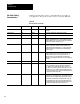
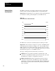
Table 2.A
Wire/Terminal
Connections for Imtermediate Nodes
For this Wire/Pair Connect this Wire To this Terminal
Shield/Drain Nonjacketed Terminal 2 - Shield
Black/White Black Wire
White Wire
Cut back - No connection
Terminal 3 (Signal Ground)
Black/Red Black Wire
Red Wire
Terminal 4 (Data A)
Terminal 5 (Data B)
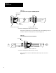
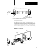
The nodes at each end of the network must be terminated. Install a jumper
wire between terminals 5 and 6 to enable the impedance built into the
module.
One (not both) of the nodes at the end of the network must have an earth
ground connection for the communication cable shield. For the node
at one end of the network, whether it is the KF3 or some other device,
connect the shield to ground by installing a jumper wire between terminals
1 and 2 of the terminal block.
CAUTION: Be sure no other node on the network has its shield
connected to ground.
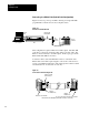
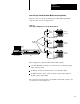
Figure 2.3 illustrates proper jumper connections for end nodes.
Figure 2.3
Jumper
Connections for End Nodes
Jumper
to
ground shield
KF3 on one end of the link
Jumper to
terminate node
SLC 500 or other device on the other
end of the link
Jumper to
terminate node
* The black wire of the white/black pair should be cut back (no connection).