
User Manual Owner manual

Installing the KF3
Chapter 2
25
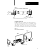
Connecting to a DH485 Network (MultiPoint Configuration)
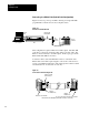
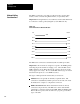
Figure 2.6 shows a network consisting of three SLC 500 programmable
controllers and one host computer station.
Figure 2.6
Connecting
to Multiple SLC 500s via the DH485 Network
DH485
Cable
Belden #9842
RS232C
Cable
Host Computer
KF3
1747C1
1 Cable
SLC 500
Controller
Link
Coupler
1747AIC
1747C1
1 Cable
SLC 500
Controller
Link
Coupler
1747AIC
1747C1
1 Cable
SLC 500
Controller
Link
Coupler
1747AIC
This configuration requires the KF3 and three link couplers:
one SLC 500 family controller is connected to each of the link couplers
with a 1747-C11 cable
the KF3 is connected to the network at one of the link couplers
the DH-485 cable consists of three segments of cable daisy-chained to
the link couplers and the KF3
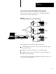
The connection between the first node (the KF3) and the link coupler to the
second node is shown in Figure 2.7.