
Install Instruc Universal I/O Chassis Owner manual
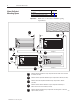
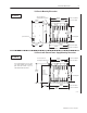
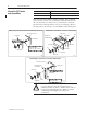
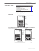
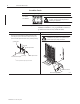
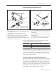
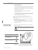
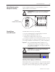
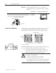
Table Of Contents
- 1771-5.60, Universal I/O Chassis, Installation Instructions
- What This Document Contains
- To the Installer
- Prepare for Installation
- Allow Sufficient Mounting Space
- Mount the I/O Chassis and Ground Bus
- Ground Your I/O Chassis
- Set the Power Supply Configuration Jumper
- Set the Switches on the Backplane Assembly
- Provide Power to the I/O Chassis
- Install Your I/O Modules
- Specifications
- Back Cover
Universal I/O Chassis2
Publication
1771–5.60 – May 1999
For these mounting dimensions See page
I/O chassis 3
I/O chassis with external power supply 3
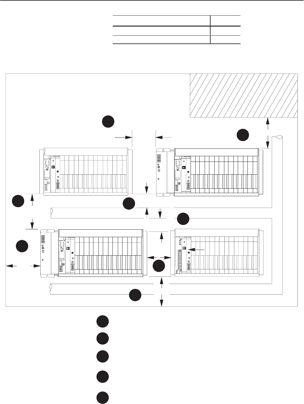
Important: Make sure you meet these minimum spacing
requirements.
B
D
A
C
Minimum
distance between a major component and the sides of an enclosure
is 102mm (4 inches).
Minimum vertical separation between major components is 153mm (6 inches).
Minimum horizontal separation between major components is 102mm
(4 inches).
Minimum vertical distance between a major component and the top or
bottom of an enclosure is 153mm (6 inches).
Minimum distance between major components and wiring ducts or terminal
strips is 51mm (2 inches).
E
D
D
A
B
C
D
E
C
1
3
082
102mm
(4”)
153mm
(6”)
51mm
(2”)
51mm (2”)
153mm
(6”)
153mm (6”)
102mm
(4”)
102mm
(4”)
E
wiring duct
wiring duct
Allow Sufficient
Mounting Space