
Install Instruc Universal I/O Chassis Owner manual
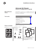
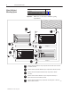
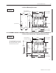
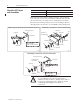
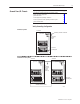
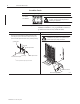
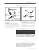
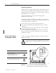
Table Of Contents
- 1771-5.60, Universal I/O Chassis, Installation Instructions
- What This Document Contains
- To the Installer
- Prepare for Installation
- Allow Sufficient Mounting Space
- Mount the I/O Chassis and Ground Bus
- Ground Your I/O Chassis
- Set the Power Supply Configuration Jumper
- Set the Switches on the Backplane Assembly
- Provide Power to the I/O Chassis
- Install Your I/O Modules
- Specifications
- Back Cover
Universal I/O Chassis 3
Publication
1771–5.60 – May 1999
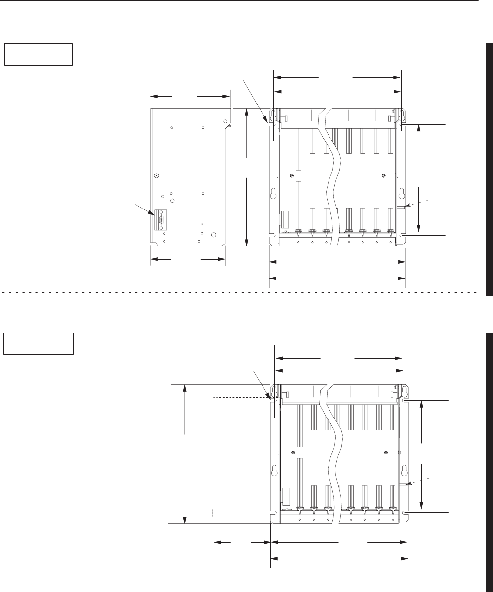
I/O Chassis Mounting Dimensions
315mm
(12.41”)
254mm
(10”)
1771
-
A2B
SS
1771-A3B1SS
193mm
1
(7.60”)
171mm
(6.75”)
356mm
(14.01”)
power
connector
grounding stud
use 1/4-20 (M6 x 10)
mounting bolts (four places)
337mm
(13.25”)
8–slot 1771–A2BSS
8–slot 1771–A2BSS
483mm
(19.01”)
12-slot 1771-A3B1SS
464mm
(18.25”)
12-slot 1771-A3B1SS
I/O Chassis with External Power Supply Mounting Dimensions
315mm
(12.41”)
254mm
(10”)
1771
-
A2B
SS
1771-A3B1SS
1771-P1
1771-P2
1771-P7
1771-PS7
Power Supply
12451-
I
91mm
(3.6”)
337mm
(13.25”)
You can mount 1771-P1, -P2, -P7 and
-PS7 power supplies on the left side
plate of the I/O chassis, or up to 5
cable-feet from the I/O chassis.
483mm
(19.01”)
grounding
stud
use 1/4-20 (M6 x 10)
mounting bolts (four places)
8–slot 1771–A2BSS
8–slot 1771–A2BSS
356mm
(14.01”)
12-slot 1771-A3B1SS
464mm
(18.25”)
12-slot 1771-A3B1SS