
Install Instruc Universal I/O Chassis Owner manual
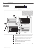
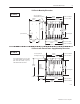
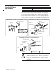
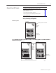
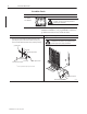
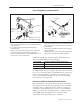
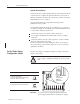
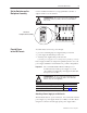
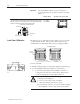
Table Of Contents
- 1771-5.60, Universal I/O Chassis, Installation Instructions
- What This Document Contains
- To the Installer
- Prepare for Installation
- Allow Sufficient Mounting Space
- Mount the I/O Chassis and Ground Bus
- Ground Your I/O Chassis
- Set the Power Supply Configuration Jumper
- Set the Switches on the Backplane Assembly
- Provide Power to the I/O Chassis
- Install Your I/O Modules
- Specifications
- Back Cover
Universal I/O Chassis 5
Publication
1771–5.60 – May 1999
To properly ground your I/O chassis See page
verify that your system-design plans are using the correct
system grounding configuration . . . . . . . . . . . . . . . . . . . . . .
5
ground the chassis . . . . . . . . . . . . . . . . . . . . . . . . . . . . . . . 6
connect equipment grounding conductors . . . . . . . . . . . . . . . 7
connect a ground bus to the grounding electrode system . . . . 7
ground shielded cables . . . . . . . . . . . . . . . . . . . . . . . . . . . .
8
Verify Grounding Configuration
enclosure
grounding electrode conductor
To
grounding
electrode
system
ground bus
Re
mo
te I/O Syste
m
s
ground
bus
ground bus
T
o
grounding
electrode
system
(single
point only)
Extended-Local I/O Systems
enclosure enclosure
I/O chassis
grounding stud
I/O chassis
grounding
stud
extended local I/O cables
19938
Ground Your I/O Chassis