
Install Instruc Universal I/O Chassis Owner manual
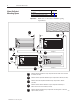
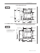
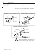
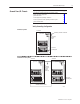
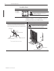
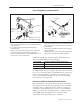
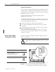
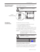
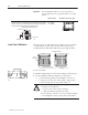
Table Of Contents
- 1771-5.60, Universal I/O Chassis, Installation Instructions
- What This Document Contains
- To the Installer
- Prepare for Installation
- Allow Sufficient Mounting Space
- Mount the I/O Chassis and Ground Bus
- Ground Your I/O Chassis
- Set the Power Supply Configuration Jumper
- Set the Switches on the Backplane Assembly
- Provide Power to the I/O Chassis
- Install Your I/O Modules
- Specifications
- Back Cover
Universal I/O Chassis6
Publication
1771–5.60 – May 1999
Ground the Chassis
This I/O chassis Has grounding stud(s) located
1771-A2BSS
1771-A3B1SS
ATTENTION: To prevent ground loops from
occurring, use only one grounding stud when
grounding your equipment.
Important: Use the following information, along with the
installation manual for your programmable controller to
ground the I/O chassis and your I/O modules.
Chassis Ground Single-point Grounding
I/O chassis side plate
star washer
nut with captive washer
ground lug
1
ground lug
nut with captive washer
W
he
n you conn
e
ct
gr
oun
d
in
g
con
d
ucto
rs
to t
he
I/O
c
h
a
ss
i
s
grounding stud, place a star washer under the first lug, then
place a nut with captive lock washer on top of each ground lug.
grounding
stud
1
Use
the cup washer if crimp-on lugs are not used.
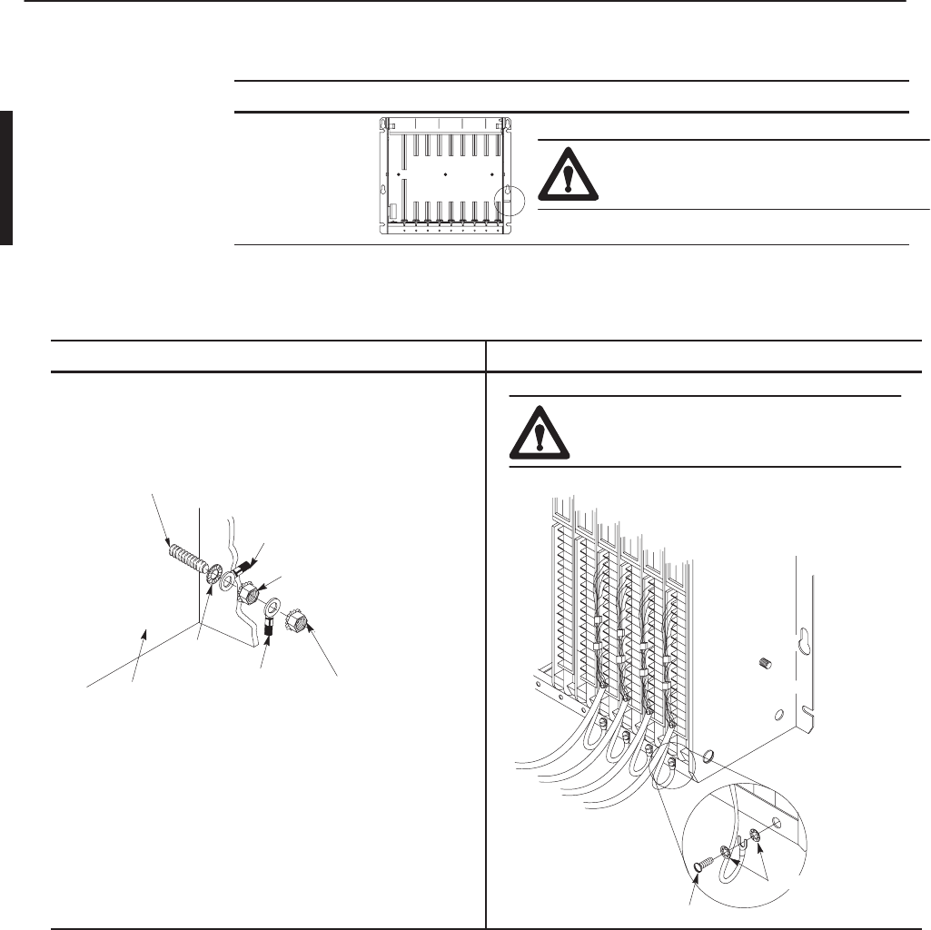
#10
thread-forming screw
external-tooth washers
19923
ATTENTION:
Use single-point grounding for
extended-local I/O systems. The systems must be
grounded properly for proper performance.