Allen Bradley Direct Communication Module (Cat. No.
Table of Contents To Our Customers . . . . . . . . . . . . . . . . . . . . . . . . . . . . . . . 1 1 To Our Customers . . . . . . . . . . . . . . . . . . . . . . . . . . . . . . . . . . . Manual's Purpose . . . . . . . . . . . . . . . . . . . . . . . . . . . . . . . . . . . Intended Audience . . . . . . . . . . . . . . . . . . . . . . . . . . . . . . . . . . . Terminology . . . . . . . . . . . . . . . . . . . . . . . . . . . . . . . . . . . . . . . . Related Publications . . . . . . . . . . . . . . . . .
ii Table of Contents Calculating Transfer Time . . . . . . . . . . . . . . . . . . . . . . . . . 7 1 Calculating Transfer Time . . . . . . . . . . . . . . . . . . . . . . . . . . . . . . Discrete Transfer Time . . . . . . . . . . . . . . . . . . . . . . . . . . . . . . . . Block Transfer Time . . . . . . . . . . . . . . . . . . . . . . . . . . . . . . . . . . Block Transfer with a PLC 3 Supervisory Processor . . . . . . . . . . . 7 1 7 1 7 4 7 6 Troubleshooting Your 1771-DCM . . . . . . . . . . . . .
Chapter 1 To Our Customers To Our Customers The following information may be helpful when using this manual: Manual's Purpose The purpose of this manual is to help you understand the intended application of your Direct Communication Module (cat. no. 1771-DCM) and operate your 1771-DCM correctly in the shortest possible time.
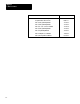
Chapter 1 To Our Customers 1 2 Title Publication 1771 ASB Remote I/O Adapter 1771 6.5.37 Programmable Controller Terms PCGI 7.2 PLC 2/05 Programming Manual 1772 6.8.6 PLC 2/15 Programming Manual 1772 6.8.2 PLC 2/02, 2/16, 2/17 User's Manual 1772 6.5.8 PLC 2/30 Programming Manual 1772 6.8.3 PLC 3 Programming Manual 1775 6.4.1 PLC 5 Family Processor Manual 1785 6.8.2 PLC 5/250 Programmer's Manual 5000 6.4.
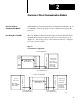
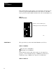
Chapter 2 Overview of Direct Communication Module Overview of Direct Communication Module Allen-Bradley has introduced the Direct Communication Module (cat. no. 1771-DCM) to meet the growing need for communication between PC processors. Describing the 1771 DCM The 1771-DCM is a chassis-mounted single-slot I/O module that allows communication between a supervisory processor and local processors (Figure 2.1). The local processor can be chassis-mounted or configured as a local or remote system.
Chapter 2 Overview of Direct Communication Module The 1771-DCM passes data table values such as command bits, status bits, and data blocks between supervisory and local processors. The supervisory processor typically writes commands and/or data table values to the local processor, and reads resulting status, diagnostic data, and data values from the local processor (or vice versa).
Chapter 2 Overview of Direct Communication Module Baud Rate/Distance Select the communication rate and distance to the supervisory proces sor as either 57.6K baud to a distance of 10,000 feet, or 115.2K baud to a distance of 5,000 feet. Transfer Method Select block transfer or discrete data transfer between the 1771 DCM and the supervisory processor.
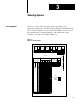
Chapter 3 Selecting Options Selecting Options Select one or more of the following options depending on your application requirements. Do this by setting switches in Switch Banks 0 and 1 on the left (metal cover) side of the 1771-DCM. To assist you, we have printed a table of switch settings for each switch bank on the module’s cover next to the switches (Figure 3.1). Figure 3.1 Tables for Switch Settings BANK 0 SW SW L A S T 1 2 RACK BAUD RATE Not Used 57.6 115.
Chapter 3 Selecting Options Each switch bank has eight switches. Set each switch to the ON (closed) position by depressing the right-hand side of the switch or to the OFF (open) position by depressing the left-hand side of the switch (Figure 3.2). Figure 3.2 Example Switch Bank 1 Switches 1 and 3 are OFF (open) 2 Shading represents the switch position 3 4 5 OPEN 6 7 8 12826 Switch Bank 0 The options that you select with Switch Bank 0 are as follows: Switch 1 Baud Rate ON (Closed) for 57.
Chapter 3 Selecting Options Switch 3 Last Rack ON (Closed) Not Last Rack OFF (Open) Last Rack If the 1771-DCM is assigned the same I/O rack number as other I/O chassis, designate whether this I/O chassis is the last chassis (has the highest starting module group number) of those assigned the same rack number. (Refer to I/O Rack Number below.
Chapter 3 Selecting Options new write block transfer from the local processor until the supervisory processor has read the previous data from the 1771-DCM. When you select unprotected data, the local processor updates the 1771-DCM continually, regardless of whether the supervisory processor has read the data from the 1771-DCM.
Chapter 3 Selecting Options Designate the I/O rack number that you assign to the 1771-DCM with Switches 1 - 6 of Switch Bank 1 (Table 3.A). Table 3.
Chapter 3 Selecting Options Switch I/O Rack Number (Octal) 1 2 3 4 5 6 30 ON OFF OFF ON ON ON 31 ON OFF OFF ON ON OFF 32 ON OFF OFF ON OFF ON 33 ON OFF OFF ON OFF OFF 34 ON OFF OFF OFF ON ON 35 ON OFF OFF OFF ON OFF 36 ON OFF OFF OFF OFF ON 37 ON OFF OFF OFF OFF OFF Switches 7 and 8 First (Starting) Module Group Number First Module Switch Group Number 7 8 0 ON ON 2 ON OFF 4 ON ON 6 OFF OFF Assign a unique stating module group
4 Chapter Connecting Cables Connecting Cables The communications channel between the 1771–DCM and a supervisory processor is the same serial communications channel as used between the 1771–ASB Remote I/O Adapter (Series A) and the scanner of a supervisory processor. You insert the 1771–DCM in a local or remote I/O chassis and configure the 1771–DCM as an I/O chassis unique to the supervisory processor.
Chapter 4 Connecting Cables Daisy Chain Hookup When using the daisy chain hookup (Figure 4.2), splice each I/O chassis into the main communication line (serial I/O channel). Install a 150 ohm terminator resistor between the terminals of Lines 1 and 2 at the scanner and at the last hookup on the main communications line to terminate both ends of the line. Figure 4.
Chapter 4 Connecting Cables Trunkline/Dropline Hookup When using the trunkline/dropline hookup, connect the 1771–DCM to the serial I/O channel trunkline using a dropline that does not exceed 100 feet in length (Figure 4.3). Connect the dropline to the trunkline using a T connector (cat. no. 1770–XG) or a station connector (cat. no. 1770–SC). There are no restrictions as to the spacing between station connectors or T connectors if you do not exceed the maximum cable distance.
Chapter 5 Using the Status Word Using the Status Word The 1771-DCM sets status/alarm bits in the upper byte of the first word transferred to either processor, regardless of whether you select block transfer or discrete data transfer. In block transfer operation, the status word is the first word of the read data block. In discrete data transfer, the status word is found in the equivalent of the first module group of the I/O chassis simulated by the 1771-DCM.
Chapter 5 Using the Status Word Bits in the status word read by the supervisory processor differ from those read by the local processor. Some bits apply only when the 1771-DCM is communicating with the supervisory processor by block transfer.
Chapter 5 Using the Status Word Bit 14 Not Used Bit 13 No Data Available Set by the 1771-DCM at power-up. The 1771-DCM rests this bit when it receives data from the supervisory processor.
Chapter 5 Using the Status Word Bit 14 Backplane Error Set by the 1771-DCM whenever it detects that a block transfer operation by the local processor was not completed on time, was out of sequence, or contained a checksum error. The 1771-DCM returns the last valid data received from the local processor. It returns zeroed data words if communications had not been established. It inhibits block transfers to the local processor until it detects a backplane reset or a scan from the local processor.
Chapter 6 Programming the 1771-DCM Programming the 1771-DCM We assume that you are familiar with block transfer programming, that you can allocate data table areas for read and write data blocks, and that you can manipulate data to and from these data blocks. We will confine this discussion to programming characteristics unique to the 1771–DCM.
Chapter 6 Programming the 1771-DCM Block Transfer and File Move Instructions Enter these instructions using the following information: BTR/BTW Module Address The module address of BTR and BTW instructions in the local processor’s program is the physical location of the 1771–DCM.
Chapter 6 Programming the 1771-DCM Figure 6.2 Local Processor Programming Example (PLC-5) Rung 2:0 PLC5 local write rung. The DCM is located in the same I/O chassis as the PLC5, and is set for block transfer. The local proces sor's write length must match the supervisory processor's read length. BTR BTW ENABLE BIT ENABLE BIT BTW N12:5 N12:0 BLOCK TRNSFR WRITE EN 15 15 Rack 0 DN Group 3 Module 1 ER Control Block N12:5 Data file N13:30 Length 17 Continuous N Rung 2:1 PLC5 local read rung.
Chapter 6 Programming the 1771-DCM First (Starting) Module Group Number (Switch Bank 1, Switches 7 and 8) The slot number will always be zero for block transfer only. Equivalent rack size for discrete data transfer only (Switch Bank 0, Switches 7 and 8). The equivalent rack size for block transfer mode is fixed at 1/4 rack. Discrete Data Transfer The supervisory processor transfers discrete data to and from the 1771–DCM automatically via its I/O scan. You do not program these transfers.
Chapter 6 Programming the 1771-DCM Example 1: Suppose you want to transfer six words, and you have configured the 1771–DCM to simulate a 3/4 I/O rack with the following address: Rack Number = 2, First Module Group = 0. Also, suppose that the 1771–DCM is located in the same chassis with the local processor, that the 1771–DCM’s actual location (RGS) is 131, that the local processor’s block transfer read block is 300 through 305, and that the block transfer write block is 200 through 205.
Chapter 6 Programming the 1771-DCM Your ladder program for the supervisory processor must place data in output image table word addresses for transfer to the 1771–DCM and move data from input image table word addresses as needed by your application. We leave this ladder logic to you because your application and processor’s set of instructions determine how you would do this.
Chapter 6 Programming the 1771-DCM Figure 6.
Chapter 6 Programming the 1771-DCM Figure 6.
Chapter 6 Programming the 1771-DCM Figure 6.6 Block Transfer Programming Example for PLC-5 Family Supervisory Processor Rung 2:2 PLC5 supervisory write rung. The DCM is connected via remote I/O to the PLC5, and is set for 57.6K baud, block transfer, and rack 3. The supervisory processor's write length must match the local processor's read length.
Chapter 6 Programming the 1771-DCM Figure 6.7 Block Transfer Programming Example for PLC-5/250 Supervisory Processor Rung 1STEP0:0 PLC5/250 supervisory write rung. The DCM is connected via remote I/O to the PLC5/250. The DCM baud rate switch setting must match that of its scanner channel. The DCM rack switches are set for rack 7. The local processor's read length must match the supervisory processor's write length.
Chapter 6 Programming the 1771-DCM BTR/BTW Module Address The module address of BTR and BTW instructions in the supervisory processor’s program is the configured address of the 1771–DCM. It is the I/O rack number and starting module group number (its slot number is always zero for block transfer) that you set using Switch Banks 0 and 1). Block Length/File Length Generally, set them to the number of words that you set for the 1771–DCM.
Chapter 6 Programming the 1771-DCM Example 2: Suppose you want to transfer 64 words, and you have configured the 1771–DCM to simulate a block transfer module in Rack 2, First Module Group = 0. Also suppose that the 1771–DCM is located in the same chassis with the local processor, and that the 1771–DCM’s actual location (RGS) is 131. In this example, you allocated data blocks for block transfer as follows: (Refer to Figure 6.4 for PLC–2/30, or Figure 6.
Chapter 6 Programming the 1771-DCM Processor/Module Compatibility Your 1771–DCM must have the following revision (or later) for compatible block transfer operation with your processor.
Chapter 7 Calculating Transfer Time Calculating Transfer Time The time required for the transfer of data from supervisory to local processor (and vice versa) is the sum of three events: Supervisory Processor and Remote I/O Scan Time Transfer Time through the 1771-DCM Local Processor Scan Time The time required for the supervisory processor to communicate with the 1771-DCM depends on whether you select discrete data transfer (up to eight words) or block transfer (up to 64 words), the number of other remo
Chapter 7 Calculating Transfer Time Total Scan (PLC-2) = Program + Processor I/O + Remote I/O Total Scan (PLC-3) = Program + Remote I/O 1771 DCM The delay from the time the 1771-DCM receives data until it is ready for data transfer is 15 ms. During this time, it detects errors and changes in status and formats data.
Chapter 7 Calculating Transfer Time Processor Multiplier PLC 2/05, 2/15 0.08 PLC 2/30 (Local) 0.08 PLC 2 Family Example Computation Suppose that a PLC-2/30 supervisory processor has a 6K program and seven assigned rack numbers and the PLC-2/05 local processor has a 2K program. There are no other block transfer modules in either the supervisory or local systems. 1. Calculate the time required to transfer eight words from supervisory to local processor. 2.
Chapter 7 Calculating Transfer Time W = Number of Words Transferred Scan = Program Scan + I/O Scan + (Multiplier) x (Number of Words Transferred) = (15 ms)(2) + 1 ms + (0.08)(8) ms = 30 ms + 1 ms + 0.64 ms = 31.6 ms Transfer Time = Supervisory + 1771-DCM + Local = 82.5 ms + 15 ms + 31.6 ms = 129 ms Solution Part 2: Additional time for two block transfer modules in the local chassis: Time (PLC-2/05) = 2(0.08 ms) x (Number of Words Transferred) = 2(0.08 ms)(64) 1 = 10.
Chapter 7 Calculating Transfer Time PLC 2 Family Supervisory Processor The time required by the supervisory processor is the sum of the program scan, processor I/O scan, and remote I/O scan. The time is lengthened by the number of enabled block transfer modules transferring data, one module after the other, and on the number of words that each module transfers.
Chapter 7 Calculating Transfer Time Solution Part 1: Time (1 Module) = (5 ms)(4.8) + (0.5 ms)(6) + 2(7 ms)(6) + (0.5)(64) + 10 = 24 ms + 3 ms + 84 ms + 32 ms + 10 ms = 153 ms Total Time (All Five Modules) = 5(153) = 765 ms (Worst Case) Solution Part 2: To calculate the worst case time for block transfer from supervisory to local processor via the 1771-DCM, add times for the 1771-DCM and local processor: 15 ms and 31.6 ms, respectively, assuming no other block transfer modules in the local chassis.
Chapter 7 Calculating Transfer Time Scanner Scan The time required for the scanner to complete a read or write block transfer depends on the number of other block transfer modules on the same scanner channel that are enabled simultaneously. Use the following procedure to calculate the time required for the PLC-3 processor to perform all block transfers on the channel. 1. Determine the number of active I/O channels on the scanner. 2. Determine the number of I/O channels with block transfer modules. 3.
Chapter 7 Calculating Transfer Time 4. Count the number of block transfer modules on the channel. If a chassis containing block transfer modules is repeated in the rack list, count chassis and modules as often as listed. 5. Count the number of I/O chassis entries in the rack list for the channel. 6.
Chapter 7 Calculating Transfer Time An I/O chassis can appear more than once in a rack list of I/O chassis. Count it and the block transfer module(s) that it contains as often as it is listed. Figure 7.1 Diagramming I/O Channels Step 1 Diagram the chassis connected in series to each channel (up to 4) of your scanner module. Then, fill in the information called fo below. Example values have been added.
Chapter 7 Calculating Transfer Time Figure 7.2 Nominal Time Table Step 2 Determine a time from the table. Example values have been added for a BTW instruction. Number of Active I/O Channels Active I/O channels containing one or more block transfer modules 1 1 2 3 4 Number of active I/O channels: 3 45 50 60 65 70 70 75 Number of active I/O channels containing one or more block transfer module: 2 85 95 2 3 4 Time from table: 70 ms 100 Time (ms) 3.
Chapter 7 Calculating Transfer Time 4. Compute the approximate read or write block transfer time for Channel 1 and Channel 3 (Figure 7.4). Figure 7.4 Computing Block Transfer for Each Channel STEP 4: Compute the read or write block transfer time. Example values have been added. Program Scan Time (Program) = = = 2.5 ms/K Words x 20K Words 2.
Chapter 7 Calculating Transfer Time Distribute block transfer instructions equally throughout your program. Place an equal number of non-block transfer rungs between block transfer rungs. For large numbers of block transfer instructions, distribute groups of block transfer rungs equally throughout your program. Place no more than four block transfer rungs consecutively in one group. Within each group, condition the next rung using the done bit of the previous block transfer instruction.
Chapter 7 Calculating Transfer Time You have a communications problem. You did not correctly connect the twin-axial cable to the scanner. You did not connect a terminator resistor to each end of the twin-axial cable. When the scanner encounters a communication fault, it tries twice to complete the transfer. It sets the error bit after the second unsuccessful try. When the scanner and/or processor detects a block transfer error, the transfer is halted.
Chapter 8 Troubleshooting Your 1771-DCM Troubleshooting Your 1771-DCM When troubleshooting your 1771–DCM, check each of the following sources in the order given for the cause of the fault: LEDs on the 1771–DCM Block transfer rungs in the ladder program of your local or supervisory processor Status bits in the status word read by the local or supervisory processor LED Display for Normal Operation Under normal operating conditions, the LEDs are lit as follows: Power (PWR) ON Serial Communication (SER CO
Chapter 8 Troubleshooting Your 1771-DCM LED BCKPLN COM Status Blinking Diagnosis The 1771-DCM turns on this LED for half a second at the com pletion of a read or write block transfer. This LED blinks when: • The local processor performs block transfers at a rate slower than once every 1/2 second. • With the 1771-DCM in protected data mode, the supervisory processor performs block transfers at a rate slower than once every 1/2 second.
Chapter 8 Troubleshooting Your 1771-DCM You assigned valid areas of data table for read and write blocks. For example, if operating in discrete data transfer mode, I/O image table addresses of the supervisory processor’s ladder program match the RGS to which you configured the 1771–DCM. Your conditioning instructions in block transfer rungs allow the rungs to turn ON and OFF. If using a PLC–2/30 supervisory processor, set the scanner for block transfer operation.
Chapter 8 Troubleshooting Your 1771-DCM Specifications Function • Provides Direct Communication Between Supervisory and Local Processors Serial Communication • Discrete Data Transfer: Up to Seven Words Plus One Status Word • Block Transfer: Up to 63 Words Plus One Status Word Transmission • 10,000 Cable Feet at 57.6K Baud • 5,000 Cable Feet at 115.2K Baud Response Time • Less than 15 ms 8 4 Interconnect Cable • 1770-CD (Belden 9463 or Equivalent) Backplane Current • 1.
Index A Application Examples, 2 3 Audience, 1 1 Module Group Number, 3 6 O Options, Selection of, 2 2, 3 1 B Baud Rate, 3 2 Block Length, 6 2, 6 11 Block Transfer, 6 6 Errors, Causes of, 8 2 C Connections to Module, 4 1 D Data Highway, 2 2 Data Transfer Block Transfer Example, 6 12 Discrete Data Example, 6 4 Data Words, Available, 5 1 Description of 1771-DCM, 2 1 Discrete Data Transfer, 7 1 E Errors, Indicated by Status Bits, 8 3 I Instructions Block Transfer, 6 2 File Move, 6 2, 6 11 K Keying, 2 3
I–2 Index Transfer Method, 3 3 Transfer Time, Block Transfer, 7 4 Example PLC-2/30 Supervisory Processor, 7 5 Example PLC-3 Supervisory Processor, 7 8 Transfer Time, Discrete Data Transfer, 7 1 Example PLC-2 Family Processors, 7 3 Troubleshooting, 8 1
Allen Bradley, a Rockwell Automation Business, has been helping its customers improve pro ductivity and quality for more than 90 years. We design, manufacture and support a broad range of automation products worldwide. They include logic processors, power and motion control devices, operator interfaces, sensors and a variety of software. Rockwell is one of the worlds leading technology companies. Worldwide representation.