
USER MANUAL 1771-DCM User Manual


Programming the 1771-DCM
Chapter 6
612
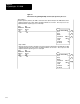
Example 2:
Suppose you want to transfer 64 words, and you have configured the
1771–DCM to simulate a block transfer module in Rack 2, First
Module Group = 0. Also suppose that the 1771–DCM is located in
the same chassis with the local processor, and that the 1771–DCM’s
actual location (RGS) is 131. In this example, you allocated data
blocks for block transfer as follows: (Refer to Figure 6.4 for
PLC–2/30, or Figure 6.5 for PLC–3 Programming)
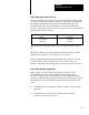
Data
Block Supervisory Processor Local Processor
Read
600 through 677 300 through 377
Write
500 through 577 200 through 277
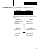
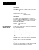
Data transfers would occur as follows for PLC–2 family processors:
Supervisory
Processor
To
Local Processor
BTW Instruction W
rites Data to the
1771-DCM from W
ords 500 through
577
BTR Instruction Reads Data from the
1771-DCM into W
ords 300 through 377
500 Status W
ord (Zeroed)
501 First Data W
ord
502 Second Data Word
:
:
577 Last Data W
ord
300 Status Word (Inserted by DCM)
301 First Data W
ord
302 Second Data W
ord
:
:
377 Last Data W
ord
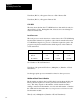
Local Processor
To
Supervisory Processor
BTW Instruction W
rites Data to the
1771-DCM from W
ords 200 through
277
BTR Instruction Reads Data from the
1771-DCM into W
ords 600 through 677
200 Status W
ord (Zeroed)
201 First Data W
ord
202 Second Data W
ord
:
:
277 Last Data W
ord
600 Status Word (Inserted by DCM)
601 First Data W
ord
602 Second Data W
ord
:
:
677 Last Data W
ord