
USER MANUAL 1771-DCM User Manual

Troubleshooting Your 1771-DCM
Chapter 8
83
You assigned valid areas of data table for read and write blocks. For
example, if operating in discrete data transfer mode, I/O image table
addresses of the supervisory processor’s ladder program match the RGS
to which you configured the 1771–DCM.
Your conditioning instructions in block transfer rungs allow the rungs
to turn ON and OFF.
If using a PLC–2/30 supervisory processor, set the scanner for block
transfer operation.
If using a PLC–3 supervisory processor, create block transfer data files.
Display status bits in the status word read by either processor by
displaying the read block of the read block transfer instruction. Refer to
your processor’s manual for the procedure.
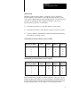
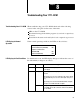
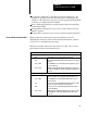
The first word in the data block is the status word. Hex codes of some
typical fault conditions are tabulated below:
Hex
Code Fault Condition
Read by Local Processor
0300
Supervisory processor is in program or test mode.
2300
No communication between the supervisory processor and its
scanner.
0900 or 2B00
1771-DCM has not received data from the supervisory proces
sor since power-up.
4100 or 8100 Number of words transferred between the supervisory proces
sor and 1771-DCM is not equal to the number read by the local
processor.
Read by Supervisory Processor
0500
1771-DCM has not received data from the local processor
since the last time it was read by the supervisory processor
.
0900 or 0D00 1771-DCM has not received data from the local processor
since power-up.
1100
Local processor is not performing block transfers due to a time
out, out-of-sequence transfer
, or checksum error
.
2300
Local processor is not performing block transfers because it
reset the backplane.
4100 or 8100 Number of words transferred between the local processor and
1771-DCM is not equal to the number read by supervisory
processor.
Errors Indicated by Status Bits