
USER MANUAL 1771-DCM User Manual

Chapter
3
31
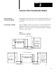
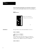
Selecting Options
Select one or more of the following options depending on your
application requirements. Do this by setting switches in Switch Banks 0
and 1 on the left (metal cover) side of the 1771-DCM. To assist you, we
have printed a table of switch settings for each switch bank on the
module’s cover next to the switches (Figure 3.1).
Figure 3.1
Tables
for Switch Settings
BAUD
RATE
DATA
PTCT
RACK
SIZE
LAST
RACK
TRANS
MTHD
SW SW SW SW SW SW SWITCH
12 3 45 6 78
57.6
NO
YES
BLOCK
DSCRT
NO
YES
1/4
1/2
3/4
FULL
Not
Used
Not
Used
00
01
02
03
04
05
07
10
11
12
13
14
15
16
17
20
21
22
23
24
25
26
27
30
31
32
33
34
35
36
37
NOTE: DO NOT USE OTHER SWITCH POSITIONS
I/O RACK
NUMBER
FIRST
MODULE
GROUP NO.
SWITCH SWITCH
12 34 5 6
78
0
2
4
6
1
2
3
4
5
6
7
P
L
C
_
2
P
L
C
-
5
&
5
/
2
5
0
P
L
C
_
3
06
ON
CLOSED
OFF
OPEN
1
2
3
4
5
6
7
8
B
A
N
K
0
1
2
3
4
5
6
7
8
B
A
N
K
1
BANK 0
BANK 1
17906
115.2
Selecting Options