(Cat. No.
Important User Information Because of the variety of uses for the products described in this publication, those responsible for the application and use of this control equipment must satisfy themselves that all necessary steps have been taken to assure that each application and use meets all performance and safety requirements, including any applicable laws, regulations, codes, and standards.
Summary of Changes Summary of Changes This edition of this publication contains new and updated information. To help you find new and updated information in this manual, we have included change bars as shown to the left of this paragraph. New Information For detailed information on this subject: See: ".5++ 2+: ,82)7/32 )'006 :+5+ '**+* 73 7.+ 0/(5'5< • " & &#& $ • " & #&#& $ • " &# " &#& $ 44+2*/; ":3 2+: 7.
Preface Using This Manual Purpose of this Manual Use this manual to help you install, configure, and operate your control coprocessor. This manual shows you examples of screens and programs to help you prepare your application programs. Important: The programming-terminal screens and programs are examples only. Your applications may be different from the examples; therefore, the content of your screens and user programs may be different.
Preface Table 2 BASIC Programming Reference (D1771ĆL01) 2 2 2 Manual Contents Publication Number 2 ) * ,#'! 1+, & + * '- % 0)% #'+ ," 2 &-%,#, +$#'! () * ,#'! +1+, & ' #,+ -,#%#,# + 2 2 + * '- % "(/+ )*(!* & .
Table of Contents Introducing the Control Coprocessor Chapter 1 Installing the Control Coprocessor Chapter 2 Getting Started with the Control Coprocessor Chapter 3 (!/2%0 "*%#2)4%1 0.$3#2 4%04)%5 !0$5!0% 4%04)%5 .$%1 .& .,,3-)#!2).- 5)2( ! 0.'0!,,!"+% .-20.
Table of Contents Using the Programming Environment Chapter 4 Developing Programs Chapter 5 Using the Ethernet Interface Chapter 6 Using the Serial Ports Chapter 7 vi (!03%1 "*%#3)5%2 1%!3% ! %23 1/'1!- /-0),% ! %23 1/'1!- %.$ ! ).!18 ),% 3/ 3(% /.
Table of Contents Interpreting Fault Codes and Displays Chapter 8 Control Coprocessor Specifications Appendix A Application Program Interface Library of Functions Appendix B ,%36)4 &.
Table of Contents DTL_READ_W . . . . . . . . . . . . . . . . . . . . . . . . . . . . . . . . . . . . . . . . . DTL_READ_W_IDX . . . . . . . . . . . . . . . . . . . . . . . . . . . . . . . . . . . . DTL_RMW_W . . . . . . . . . . . . . . . . . . . . . . . . . . . . . . . . . . . . . . . . . . DTL_RMW_W_IDX . . . . . . . . . . . . . . . . . . . . . . . . . . . . . . . . . . . . . DTL_SIZE . . . . . . . . . . . . . . . . . . . . . . . . . . . . . . . . . . . . . . . . . . . . . . DTL_TYPE . . . . . . . . . . .
Table of Contents Using the PCBridge Software Appendix D && $ - ! ) + ( %*) ' % ), ' %$ *' ) %$ &) %$( % $ #%'. % *" % $ #%) ".
Chapter 1 Introducing the Control Coprocessor Chapter Objectives This chapter introduces the applications and functions of the control coprocessor. The chapter also covers the hardware components and the programming capabilities of a control coprocessor.
Chapter 1 "'%# ( " ' #"'%# #$%# &&#% You can use the control coprocessor for applications such as: calculating complex math or application-specific algorithms using C and/or BASIC programs production scheduling or historical-data logging/tracking high-speed search and compare of very large files or look-up tables protocol conversion for interfacing a programmable controller with a variety of field devices ControlĆCoprocessor Modules The control coprocessor consists of a main module and an optiona
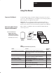
Chapter 1 5;96,<+15/ ;0- 65;963 6796+-::69 Hardware Overview Table 1.B describes the hardware elements for the main module. Table 1.B MainĆModule Hardware Elements Hardware Element " # $ #>1;+0 : Description %:- ;0- 9-:-; :>1;+0 ;6 9-151;1)31A- ;0- +65;963 +6796+-::69 &0-5 ;0- :-91)3 -?7)5,-9 46,<3- 1: 15:;)33-, <:- ;0- 2-@:>1;+0 ;6 9-151;1)31A- ;0- +6796+-::69 6<9 :;);<: 15,1+);69: 796=1,- 15.
Chapter 1 /530&6%+/) 5*' 0/530- 0130%'4403 Table 1.C describes the hardware elements for the optional serial expander module. Table 1.C Serial Expander Module Hardware Elements Hardware Element ':48+5%* Description *+4 +4 # <104+5+0/ 413+/)<-0#&'& ,':48+5%* *' 104+5+0/ +4 64'& 50 3'+/+5+#-+;' 5*' %0/530- %0130%'4403 8+5*065 %:%-+/) 108'3 +41-#: *' <%*#3#%5'3 #-1*#/6.'3+% &+41-#: 4*084 +/(03.#5+0/ 0/ 5*' 45#5' 0( 5*' %0/530%0130%'4403 #4 1307+&'& $: 64'3 130)3#.
Chapter 1 #(&$ ) # ( $#(&$! $%&$ ''$& control coprocessor can initiate directĆaccess communication ($ - )' & " "$&, ' ' $+# & $) $ #$( # ($ %&$ & " ,$)& - %&$ & "" ! $#(&$!! & ($ ')%%$&( ( ' !!' PLCĆ5 controlĆlogic program can initiate directĆ access communication ($ ( $#(&$! %&$ ''$& ' ' $+# & PLCĆ5 controlĆlogic program can initiate backĆ plane communication + ( ( $#(&$! %&$ ''$& # & ( $## ( "$ * - &$ & "" ! $#(&$!! & $#(&$! $%&$ '
Chapter 1 ',*( - #'! ," (',*(% ()*( ++(* #+ * , (* %( $2 * '+ * *#, (&&-'# , + in the same chassis /#," 2 (* &#'# 2 )*(!* &2 & % (',*(%% * .# ," $)% ' Programming Overview 2 2 2 (* 2 )*(!* && % (',*(%% * &(, #'$ (&&-'# , + from a remote chassis /#," ," )*(!* && % (',*(%% * .
Chapter 1 ProgramĆDevelopment Software The PCBridge software package (1771-PCB) operates on a DOS- based personal computer. This software package supports offline and online user activities.
Chapter 1 Programming Languages You develop C, BASIC, and assembler programs using the PCBridge software. You can also develop and edit BASIC programs on the control coprocessor using a terminal or a personal computer for terminal emulation. See the OS-9 C Language User Manual, publication 1771-6.5.104; the OS-9 Assembler User Manual, publication 1771-6.5.106; and the OS-9 BASIC User Manual, publication 1771-6.5.103, for more information on these languages.
Chapter 2 Installing the Control Coprocessor Chapter Objectives This chapter provides instructions on how to install your control-coprocessor main module and serial expander module.
Chapter 2 &+, $$#&! ," '&,*'$ '(*' ++'* Select a Power Supply 1 Before you install your control coprocessor, select an appropriate power supply. See the Control, Communication and Information Product Catalog, publication ICCG-1.1, for backplane current requirements. To determine the size of power supply that you require: 1. Record the total current draw for all I/O modules in the chassis. 2. Record the current draw for the programmable controller or adapter module in the chassis. 3.
Chapter 2 Install the ControlĆ Coprocessor Battery The 1770-XYC battery ships with the control coprocessor and requires special handling. See Allen-Bradley Guidelines for Lithium Battery Handling and Disposal, publication AG-5.4. A red BATT status LED on the main module indicates that the battery needs replacement. Replace the battery while the module is powered so that your programs are maintained in memory.
Chapter 2 5. Place the battery and the wires in the main module. 6. Install the battery cover. 7. Using an erasable marker, record the battery-installation date. Disposing of the Battery Refer to the Allen-Bradley Guidelines for Lithium Battery Handling and Disposal, publication AG-5.4. Do not dispose of lithium batteries in a general trash collection when their combined weight is greater than or equal to 1/2 gram. A single 1770-XYC battery contains .
Chapter 2 %)* ##!% * &%*(&# &'(& ))&( Install the Keying Bands You receive plastic keying bands with each I/O chassis. Insert the keying bands in the backplane sockets of the I/O chassis, using the numbers beside the backplane connector as a guide. See Figure 2.1 and Figure 2.2. Figure 2.
Chapter 2 "&' " ' #"'%# #$%# &&#% Set Switch Configurations for the Main Module For this communication: i ti The COMM0 port has no switches to configure. Set the COMM1 switches to configure the 25-pin asynchronous communication port.
Chapter 2 ! ! ! Install the Control Coprocessor Install the control coprocessor in either direct-connect or standalone mode.
Chapter 2 #$ $ $" !" ## " Connect Control Coprocessor to Programmable Controller To connect the control coprocessor to the PLC-5 programmable controller: ATTENTION: Avoid bending pins when installing the connector header into the PLC-5 programmable-controller side connector. Also, avoid bending pins when installing the control coprocessor onto the connector header. 1. Place the PLC-5 programmable controller on a flat, anti-static surface with the side connector face up. 2.
Chapter 2 !" " " !! Install the Direct-Connect Control Coprocessor To install the PLC-5 programmable controller and control coprocessor in the 1771 I/O chassis: Important: If you are using the 1771 chassis with the locking bar rather than the locking tabs, refer to the Universal I/O Chassis Installation Data, publication 1771-2.210, for information on use. 1. Verify that power is OFF to the 1771 I/O chassis. 2.
Chapter 2 Standalone Installation You can place the control coprocessor in any available slot in the I/O chassis with the following limitations: We recommend that you configure the chassis for 1-slot addressing. The serial expander module, when used, must reside in the same module pair (under the same locking tab) as the main module. If you have two control coprocessors, place them in different module pairs. Two coprocessors cannot be placed under one locking tab.
Chapter 2 Relay Contact Output Modules Product Data, publication 1771-2.181, for more information.
Chapter 3 Getting Started with the the Control Coprocessor Chapter Objectives This chapter provides instructions on how to set up your control coprocessor for communication by: setting up your programming terminal setting up configuration parameters for the interface between the programming terminal and the control coprocessor testing the interface by completing the interface tasks For information on: Connect the Programming Terminal See page: )((! -%(# -$! *+)#+ ''%(# -!+'%( & 3 !&! -%(# -$! *+
Chapter 3 '' " ' %' ) ' ' #"'%# #$%# &&#% Connect the programming terminal to the COMM0 port—default terminal port—of the main module. See Appendix C for cable and connector information. Figure 3.1 Personal Computer to Control Coprocessor Connection #"'%# #$%# &&#% % #!!(" ' #" " % #%' Select the Programming Interface The programming terminal that you select determines how you program the control coprocessor.
Chapter 3 See Appendix D for more information. See Chapter 5 and Appendix B for more information on the A-B interface libraries. To install the software: 1. Insert the first disk. 2. At the DOS prompt, type install dest_drive: and press [Return]. For example: if your source drive is b: and you want to install the software on your hard drive c:, then type; b:install c: and press [Return].
Chapter 3 $$ $ "$ % $ $ $" !" ## " Figure 3.3 Download the PCBridge Software DIRECTORY STRUCTURE 6. Press [Return] to begin installing the software. The percentagecomplete graph increments as the software is loaded. 7. Install the remaining disk(s) when the system prompts you. Figure 3.4 Files to Modify Important: After you have installed the disks, the system informs you of any files that you must modify—e.g., AUTOEXEC.
Chapter 3 Access the PCBridge Software Access the PCBridge software from the DOS command line by typing pcb and pressing [Return]. See Figure 3.5. Figure 3.5 PCBridge Main Menu Note that the +PCB2 line at the bottom of the screen is a status line. Among other information that it provides, it informs you of the status of the link between the personal computer and the control coprocessor.
Chapter 3 Configure Communication Parameters To configure parameters for the communication interface between the personal computer and the control coprocessor: 1. Select C) Configuration Options on the PCBridge main menu. You get the PCBridge Configuration Options screen. See Figure 3.6. Figure 3.6 PCBridge Configuration Options Screen 2. On the PCBridge Configuration Options menu, select C) Communication Parameters. See Figure 3.7. Figure 3.
Chapter 3 3. On the PCBridge Communications Parameters screen, select the parameters for communication with the control coprocessor. These parameters are the default setup of the control coprocessor: 9600 baud no parity 8 data bits 1 stop bit See Appendix A, Control-Coprocessor Specifications, for other available rates of communication.
Chapter 3 Figure 3.
Chapter 3 Create a Test Directory At the $ prompt, type makdir followed by a space and the name of the test directory that you want to create; then, press [Return]. Change your working directory to the one that you just created. See Figure 3.10. Figure 3.10 OSĆ9 CommandĆLine Interface Make Directory and Change Directory PCBridge Microware’s PC hosted OS-9/680x0 Development System Welcome to PCBridge $ pd $ makdir TEST_DIR $ dir Directory of .
Chapter 3 Configure the Default Startup Parameters Configure the default startup parameters of the control coprocessor using the CC_CFG utility. See Figure 3.11. Figure 3.
Chapter 3 Configure System Memory Configure the control coprocessor system memory using the MEM_CFG utility. You can configure the size of the following non-volatile memory sections: RAM disk—page 3-12 user memory—page 3-13 module memory—page 3-15 See Figures 3.12 through 3.20 for an example using the MEM_CFG utility. Figure 3.
Chapter 3 RAM Disk The RAM disk is an emulated drive that resides in Random Access Memory (RAM). You can store and access any files on a RAM disk. The default size of the non-volatile RAM disk is 64 Kbytes. ATTENTION: Changing the size of the non-volatile RAM disk will reformat it. Back up the disk data before changing the RAM-disk size. To configure the non-volatile RAM disk: 1.
Chapter 3 Non-Volatile User Memory This is a non-volatile area of memory that is not known to the operating system; therefore, any data stored here remains intact through resets and power cycles. This non-volatile memory is controlled by user programs. This area of memory is basically a storage area for data.
Non-Volatile Memory Example User Program MY_MEM.C #include
Chapter 3 ATTENTION: This program illustrates the use of non-volatile user memory in its simplest form. The control-coprocessor MEM_CFG function only supplies a pointer and size to the non-volatile user memory. It is the responsibility of the user to manage the memory appropriately. The program stores the value of the pointer on initialization. It then performs subsequent checks to verify that the pointer value has not changed.
Chapter 3 NVMM Utility With the NVMM utility, you can: move modules from OS-9 to non-volatile module memory list all modules in the non-volatile module memory enable deletion of modules in the non-volatile module memory delete modules from the non-volatile module memory Syntax for the NVMM utility is: NVMM -M [module] NVMM -L NVMM -D Moves module into non-volatile module memory Lists all modules in non-volatile module memory Enables deletion of modules in non-vol
Chapter 3 Figure 3.
Chapter 3 See Figure 3.19 for an example MY_MEM boot screen. See page 3-14 for the source file, MY_MEM.C. Figure 3.19 MY_MEM Boot Screen PCBridge Microware’s PC hosted OS-9/680x0 Development System $MY_MEM $ Time of last boot ->Wed Jul 22 12:23:03 1994 Time of this boot ->Wed Jul 22 18:12:08 1994 Boot count = 3 Allen-Bradley Control Coprocessor Copyright 1994, Allen-Bradley Company, Inc. All Rights Reserved Series/Revision A/E (1.
Chapter 3 View ControlĆCoprocessor Current Status Use the CC_STATUS utility to view the current status of the control coprocessor. See Figure 3.21 for an example screen. Figure 3.21 CC_STATUS Screen PCBridge Microware’s PC hosted OS-9/680x0 Development System $ CC_STATUS Allen-Bradley Control Coprocessor Status Series/Revision: .............. PLC-5: ........................ Expander: ..................... Battery: ......................
Chapter 3 Set Up a Password File After the control coprocessor executes the startup file, it executes the login file. This file must have the appropriate entries for the login to execute. If the control coprocessor does not find the DD/SYS/PASSWORD file, it executes the OS-9 shell. Important: When using Ethernet, you must have a password file in the /DD/SYS directory. When you are not using Ethernet, the password file is optional.
Chapter 3 Send the Text File to OSĆ9 To send the TEST.TXT file to the OS-9 RAM disk: 1. Select S) Send file to OS-9 on the PCBridge main menu. See Figure 3.22. Figure 3.22 Select Send File on Main Menu 2. Enter the name of your text file in the prompt window. See Figure 3.23. Figure 3.23 Enter Name of Test Text File to Send to OSĆ9 PCBridge Microware’s PC hosted OS-9/680x0 Development System Welcome to PCBridge Enter filename or Transfer TAG: test.
Chapter 3 3. Select the file transfer type T) Text. See Figure 3.24. Figure 3.24 Select File Transfer Type PCBridge Microware’s PC hosted OS-9/680x0 Development System Welcome to PCBridge Select File Transfer Type B) H) T) Q) VT100 Binary Help Text Quit file transfer 16:05 -CA -PR -LO -LF -LE +XO -CT CD COM1 9600N81 PCBridge The PCBridge software automatically invokes Kermit and downloads the text file. 4.
Chapter 3 5. At the $ prompt, type dir and press [Return]. Observe that the text file was successfully transferred to the RAM disk . See Figure 3.26. Figure 3.26 Check Directory for Test File PCBridge Microware’s PC hosted OS-9/680x0 Development System Welcome to PCBridge $ dir Directory of . 16:07:18 test.txt $ list test.text VT100 6. 16:05 -CA -PR -LO -LF -LE +XO -CT CD COM1 9600N81 PCBridge At the $ prompt, type list test.txt and press [Return].
Chapter 4 Using the Programming Environment Chapter Objectives This chapter provides an example of creating and compiling a C program using the PCBridge software and the DOS editor; it then shows you how to transfer the program to the control coprocessor. The chapter also provides an example of a BASIC program.
Chapter 4 Figure 4.1 C Test Program This example creates a test file named HELLO.C. 4. Compile a C Test Program Use the exit function on your text editor to return to the PCBridge main menu. To compile the C test program: 1. Select B) Build on the PCBridge main menu. 2. Enter the name of the test file and press [Return]. See Figure 4.2. Figure 4.
Chapter 4 The C cross-compiler function compiles the test file. See Figure 4.3. Figure 4.3 Cross Compiling C Test File See the OS-9 C Language User Manual, publication 1771-6.5.104, and Appendix D for more information on setting compiler options. 3. Use the exit function on your text editor to return to the PCBridge main menu. The result of the build function is a binary, executable file of the program named HELLO.
Chapter 4 In OS-9, you type the full file name to execute the command. In our example, the full file name is HELLO. The executable file for OS-9 does not have an extension—as compared to an executable DOS file, which has a .COM, .EXE, or .BAT extension. 3. Select B) Binary on the Select File Transfer Type screen. See Figure 4.5. Figure 4.5 Select File Transfer Type The C test file is sent to the control coprocessor via Kermit. You see the screen illustrated in Figure 4.
Chapter 4 Confirm File Passage to the Control Coprocessor To confirm that the C file is resident in the control coprocessor: 1. Select O) OS-9 Terminal on the PCBridge main menu. You get the control-coprocessor OS-9 command-line interface. The C file that you previously sent to the control coprocessor should reside in the directory that you last accessed on OS-9. 2.
Chapter 4 The following example program—HELLO.BAS—is the BASIC version of the C example program. rem hello.bas rem ******************************************************************** rem rem This program is used as an example so you can learn the mechanics rem of writing a Basic program using the control coprocessor. rem rem ******************************************************************** rem Declare some variables to be used later in the program.
Chapter 4 Example Program to Access RAM Disk Refer to the following C program (CAT.C) as an example of accessing the control-coprocessor RAM disk. Note the use of standard C library functions—e.g., fopen(), getc(), and fclose()—to access RAMdisk files. You create the file, compile it, and send it to OS-9 as a binary file. Then, you run the C program on OS-9. /***** cat.
Chapter 4 ! " $ " /* * Now, as long as we have files on the command line to process, * open them, read them, and output them to standard output. */ for ( i = 1; i < argc; i++ ) { /* * Remember, fopen() returns a file pointer. If the file * pointer returned points to NULL, the file couldn’t be * opened. Exit and tell the user why. */ infil = fopen ( argv[i], “r” ); if ( infil == NULL ) { fprintf ( stderr, “*** cat: unable to open %s.
Chapter 5 Developing Programs Chapter Objectives This chapter describes the library of commands and executable functions available with the control coprocessor. You will also learn when and how to use them for communication with a programmable controller. For information on: See page: ) !( ) . $ )% *( *$ )!%$( . (!$ *$ )!%$( . (!$ *$ )!%$( . (!$ (( !$()'* )!%$( . (!$ *$ )!%$( . (!$ .
Chapter 5 - #&'!% )& ) $* What Is the Application Program Interface? The Application Program Interface (API) is a set of library routines used to interface your programs with the control coprocessor. The following are the categories of functions available in the API library. Table 5.
Chapter 5 ( !" $! $ % How to Use DTL Functions Use the DTL library of commands to access real-time data from the data table of a direct-connect PLC-5 programmable controller. The data is transferred between the control coprocessor and the PLC-5 processor via the connector interface between the two devices. This section defines the available commands. For more details, see Appendix B, Application Program Interface Routines.
Chapter 5 & ! " " # Table 5.
Chapter 5 - $'("& )' ) %* Table 5.E DTL Conversion Functions Function What It Converts 0 /+ )) / +' !'*+ + 0+/( .') .
Chapter 5 How to Use BPI Functions The control coprocessor communicates with a standalone-mode programmable controller using backplane-interface (BPI) functions. The communication is via the 1771 I/O chassis backplane. You can also use the BPI functions when you have a PLC-5 programmable controller directly connected to the control coprocessor. For backplane communication, the control coprocessor appears to the programmable controller as a 16-bit, bidirectional I/O module.
Chapter 5 How to Use Message Instructions The control coprocessor can receive unsolicited messages from the PLC-5 programmable controller. Two types of messages are supported: read data (word-range) from the control coprocessor write data (word-range) to the control coprocessor The control coprocessor supports up to 32 unsolicited messages. The control-coprocessor message numbers are 0-31 (ASCII).
Chapter 5 % !" #! # $ Figure 5.1 MSG Instruction DataĆEntry Screen (MG Control Block) MESSAGE INSTRUCTION DATA ENTRY FOR CONTROL BLOCK MG10:10 Communication Command PLC-5 Data Table Address: Size in Elements: Local/Remote: Remote Station: Link ID: Remote Link Type: Local Node Address: Destination Data Table Address: Port Number PLC-3 Word Range Write N7:3 1 LOCAL N/A N/A N/A 00 “30” 3A BLOCK SIZE IS 56 Press a key to change a parameter or to accept parameters.
Chapter 5 * #$ " &# & !' This section defines the MSG functions that process unsolicited messages from a PLC-5 programmable controller. See Appendix B, Application Program Interface Routines, for more information. Read/Write MSG Functions Use read/write MSG functions to process unsolicited MSG instructions from a PLC-5 ladder-logic program. See Table 5.G. Table 5.
Chapter 5 - $'("& )' ) %* For example, a PLC-5 programmable controller initiates an unsolicited READ MSG instruction to the control coprocessor. The READ MSG instruction transfers one word of data. The order of events is: ! '&+)'$ '()' **') ()' ) % ) *('& * ."+! ') +! & ! ') +)" )* "& +! ()' ) % * '& +! '& .') +! + . * * &+ Note: ! ,& +"'& .
Chapter 5 ) #$ " %# % !& Important: For the 1771-DMC1 and -DMC4 modules, the default size allows you to create 1024 TAGs; the -DMC module default size is zero. Use the following sections to select the appropriate TAG function for your application. See Appendix B, Application Program Interface Routines, for the following information on these TAG functions: description, required parameters, condition values, and a C program example.
Chapter 5 !0!'*+%)# ,*#, (- How to Use CC Utility Functions This section covers CC utility functions of the control coprocessor such as: initialization error handling ASCII display interface functions synchronizing a control-coprocessor calling task to a PLC-5 programmable-controller ladder-logic program scan Initialize ControlĆCoprocessor Function Use the CC_INIT function to initialize the control coprocessor.
Chapter 5 Synchronization Function Use the CC_PLC_SYNC function to synchronize the control-coprocessor calling task to the PLC-5 programmable-controller ladder-program scan. This function automatically puts the current application to sleep until the start of the next PLC-5 program scan. Because of the multi-tasking feature of OS-9, it is most effective to synchronize only one priority task to the PLC-5 programmable-controller ladder-program scan.
Chapter 5 + "%& $ '% ' #( Prepare Programs for DirectĆConnect Mode In direct-connect mode, the control coprocessor can communicate directly with a PLC-5 programmable controller using DTL and MSG functions. Also, in direct-connect mode, you can use BPI functions for backplane communication with a programmable controller. See page 5-18 for more information on programs using BPI functions. ATTENTION: The control coprocessor does not incorporate hardware memory protection between processes.
Chapter 5 Link API Functions to Programs In C and assembler programs, ABLIB.L provides the interface (link) to the library of control-coprocessor API functions. In BASIC programs, AB_BAS provides the interface (link) to the library of control-coprocessor API functions. In C, BASIC, and assembler programs, use the CC_INIT function—use AB_BAS(0) for BASIC programs—to initialize the control coprocessor.
5-16 /********************************************************************** * DTL_W_R.C — This program uses both the DTL_WRITE_W and DTL_READ_W * functions. It writes a single word to the PLC5’s N7:0 file and then * reads it back. The copro then copies the data to the 4-digit display * on the expander module. It will do this forever until the program * is terminated with a CTRL-E or a kill command from the OS-9 command line.
Chapter 5 % ! ! " Sample BASIC Program The following is a BASIC programming example that illustrates the interface to various API functions. The program uses CC_ERRSTR to copy the status of the various functions and display the string to the terminal—i.e., CC_INIT, DTL_INIT, DTL_CLOCK, and DTL_READ_W. $ # " $" ' " " # $ # $ ! & rem **************************************************************************** rem * DEMO.
Chapter 5 ' !" #! # $ Prepare Programs for Standalone Mode In standalone mode, use BPI_ functions to communicate with a programmable controller. ATTENTION: The control coprocessor does not incorporate hardware memory protection between processes. It is the user’s responsibility to ensure that programs do not overwrite memory used by other programs or by the operating system. This could result in unpredictable system operation.
Important: The CC_INIT function is used in the following program. Call the CC_INIT function first and once only in your program. /********************************************************************** * bt_w_r.c * This program uses both the BPI_WRITE and BPI_READ functions. It * continuously triggers the PLC to do block transfer writes to the * coprocessor.
Chapter 5 % ! ! " Sample BASIC Program The following is a BASIC programming example. It uses both BPI_WRITE and BPI_READ functions to trigger programmablecontroller block-transfer writes and reads.
Chapter 5 Sample ControlĆLogic Program The following is a control-logic programming example. This control-logic program initiates a block-transfer write and a read when triggered by the control coprocessor. See the sample C—on page 5-18—and BASIC— on page 5-20—control-coprocessor programs. Rung 2:0 This block-transfer write will be triggered when bit 10 of the input image is set by the control coprocessor.
Chapter 6 Using the Ethernet Interface Chapter Objectives This chapter provides an overview of the Ethernet local area network capability of the control coprocessor.
Chapter 6 & $ ' ' %$ ' $' % OS-9/Internet provides utilities for file transfer (FTP) and terminal connection (TELNET) to remote systems on the network. OS-9/Internet also provides socket-library functions that you use to write network client/server application programs. See the OS-9 Internet Software Reference Manual, publication 1771-6.4.11, for information on FTP and TELNET utilities and OS-9 socket library. Important: BASIC users cannot reference socket-library functions directly.
Chapter 6 Addresses for the Ethernet Port You must have two separate and unique addresses for the controlcoprocessor Ethernet port: software configurable Internet Protocol (IP) address and host name that you acquire from your network manager hardware Ethernet address that is assigned to the control coprocessor by Allen-Bradley at the factory—see the section on configuring the Ethernet port to identify this address on page 6-11 Acquiring Your IP Address If you are adding the contr
Chapter 6 Modifying the Ethernet Configuration Files Make a list of all the hosts with their IP addresses that are on the same physical network as the control coprocessor. Also, make a list of all the hosts with their IP addresses that are on other networks with which you will communicate regularly through a gateway. You will use this information to update the configuration files.
Chapter 6 Figure 6.1 List of Hosts on Network HOSTS.EQUIV File The file C:\INET\HOSTS.EQU is required for the OS-9 Internet database INETDB but is not used by the control coprocessor. Do not modify this file. A sample is shown in Figure 6.2. DOS limits file names to eight characters—not including a 3-digit extension—and thus PCBridge renames the file to HOSTS.EQU. However, the OS-9 name is . Figure 6.2 List of HOSTS.
Chapter 6 NETWORKS File Change file C:\INET\NETWORKS to include a line for the network to which the control coprocessor will be physically attached, giving the domain name and the subnet address of the domain. Also, include the aliases “ethernet” and “localnet.” A sample NETWORKS file is shown in Figure 6.3. Figure 6.3 List of NETWORKS File PROTOCOLS File The file C:\INET\PROTOCOL is required for the Internet database. Do not change the file.
Chapter 6 Figure 6.4 List of PROTOCOLS File SERVICES File The file C:\INET\SERVICES contains standard Internet information followed by information that applies to your system. If you write socket-library programs to establish application-specific servers, place the “well-known” port numbers of your new services at the end of this file. We recommend that you use numbers larger than 3000 for your services. See Figure 6.5 through Figure 6.8 for an example.
Chapter 6 Figure 6.5 List of SERVICES File (Sheet 1) Figure 6.
Chapter 6 Figure 6.7 List of SERVICES File (Sheet 3) Figure 6.
Chapter 6 STARTINET File The STARTINET procedure file is used to start the network. Edit the second (setip) line of file C:\INET\STARTINE by inserting the following information as appropriate for your network: IP address broadcast address subnet mask host name (optional) target gateway address (optional) IP Address The IP address is the only required parameter on the setip line, as shown below. setip x.x.x.x x.x.x.x. x.x.x.x node_name x.x.x.
Chapter 6 The STARTINET procedure file is used to start the network. This file indicates which network daemons—e.g., FTP, TELNET, INTERD, SNMPD—are loaded at reset. See Figure 6.9 for an example STARTINET file. The example file shipped in revision 1.20 and later of the PCBridge software (1771-PCB) includes the startup of the INTERD and SNMPD daemons. You can modify this file to choose which daemons are started for your system. A line started with an asterisk (*) is a comment line.
Chapter 6 Figure 6.10 List Ethernet Hardware Address Configuring the Ethernet Port To download the Ethernet configuration files to the control coprocessor and initialize the Ethernet port: 1. Select I) Internet Utilities on the PCBridge main menu. 2. Select S) Setup OS-9 Internet on the next menu. This causes the configuration files to be sent to the control coprocessor. These files will be stored in the SYS directory on the control-coprocessor RAM disk. 3.
Chapter 6 FTP Send Session The following example shows how you might conduct an FTP send session: Important: The following send session is an example only. It represents how one network is set up and accomplishes an FTP session. 1. At the $ prompt, list the file to transfer. See Figure 6.11. Figure 6.11 Starting FTP 2. At the $ prompt, type ftp and press [Return]. See Figure 6.11.
Chapter 6 Figure 6.12 FTP Help 5. At the ftp prompt, type connect and press [Return]. See Figure 6.13. Figure 6.13 Connect to Remote Network 6-14 6. At the (to) prompt , enter the name of the remote host. For this example, the remote host is group_2. 7. Enter user information (username and password) at the prompt. See Figure 6.13. We receive a login confirmation message. 8. At the ftp prompt, type pd and press [Return] for the current remote network directory name.
Chapter 6 10. At the ftp prompt, type dir and press [Return] to get a list of files in the remote directory. See Figure 6.14. Figure 6.14 Connect to Remote Subdirectory 11. At the ftp prompt, type send hosts.equiv and press [Return]. You receive status information confirming the file transfer. See Figure 6.15. Figure 6.15 FTP Send 12. At the ftp prompt, type dir and press [Return]. The remote directory now contains the transferred file. See Figure 6.15.
Chapter 6 FTP Get Session The following example shows how you might conduct an FTP get session. Important: The following ftp get session is an example only. It represents how one network is set up and we accomplished an FTP session. For this example session, we continue the previous FTP send session and retrieve the file we sent to a remote directory. 1. At the ftp prompt, type get and press [Return]. See Figure 6.16. Figure 6.16 FTP Get 6-16 2.
Chapter 6 Using the OSĆ9/Internet TELNET Utility This utility provides user-interface communication to other nodes on the Internet system. The TELNET utility provides the ability to log on to remote systems using the control coprocessor and your screen as a terminal connected to the remote host. See the OS-9 Internet Software Reference Manual, publication 1771-6.4.11, for more information on the TELNET utility and commands available.
Chapter 6 Figure 6.18 TELNET Connection to Remote Network 4. At the (to) prompt, enter the name of the the remote host to which you want to attach. For this example, the name of the remote host is group_2. 5. Log in and enter the account password. The response shows successful log in. See Figure 6.18. 6. At the Super: prompt of the remote host, type dir and press [Return] to list the directory. See Figure 6.19. Figure 6.
Chapter 6 7. At the Super: prompt of the remote host, type del host.equiv and press [Return]. The example deletes the file that was transferred to the remote host in the previous FTP send session. See Figure 6.20. Figure 6.20 Telnet Delete File and Log Out 8. At the Super: prompt of the remote host, type dir and press [Return] to list the directory contents. See Figure 6.20. The file HOST.EQUIV is no longer listed in the directory. 9.
Chapter 6 ! ! ! ! Analogy to Client/Server Application A simple analogy to the client/server application is the time-and-temperature service that is provided by the local telephone company. To acquire the time and temperature, you: look up time and temperature in the telephone directory dial the number receive an announcement of the time and local temperature hang up the telephone The following flow chart shows a client/server analogy to the time-and-temperature operation.
Chapter 6 ! ! ! ! The following flow chart shows a client/server interface.
Chapter 6 Using the INTERD INTERCHANGE Daemon INTERD is a PCCC INTERCHANGE server daemon that provides communication between the control coprocessor, its attached PLC-5 processor, and a host computer running INTERCHANGE software via the Ethernet connection of the coprocessor. INTERD is included in revision 1.20 or later of the PCBridge software (1771-PCB) and requires Series A Revision E (1.30) or later firmware in the control coprocessor.
Chapter 6 & " ' ' %" ' "' % All external access to the control coprocessor’s user memory is through the TAG table of the coprocessor. The TAG functions provide a way for you to specify access to control-coprocessor memory. The memory of the tagged area can be of any data type—e.g., char, short, float, etc.—or combination of data types. It is your responsibility to understand the layout of the tagged memory. Transmission or reception of tagged memory data is done as a “byte stream.
#include typedef struct { unsigned make; char model; char type; char color; unsigned year; }CAR; main(){ unsigned id; CAR car; /* id for tag definition */ /* car structure pointed to by tag */ CC_INIT(); /* init the coprocessor TAG_DEFINE (&id,&car,”Car”,sizeof(car),TG_MODIFY); /* define the tag car.make = car.model = car.type = car.color = car.year = 0; /* init data while (1) { TAG_LOCK (id,CC_FOREVER); /* prevent concurrent access on tagged data car.
#include ”dtl.
unsigned char pccc_rpl[275]; void main( int argc, char** argv ){ unsigned long iostat; unsigned long rpl_siz; DTSA_BKPLN addr; DTL_INIT( 1 ); /* function completion value */ /* size of pccc reply */ /* structured address */ /* Initialize the Data Table Library */ DTL_C_CONNECT( NI_ID, HOSTNAME, 0); /* Connect */ addr.atype = DTSA_TYP_BKPLN; addr.
Chapter 6 union { unsigned tmp; unsigned char c[4]; } u; unsigned make, year; unsigned char model, type, color; u.c[0] = pccc_rpl[13]; /* get the make from the reply buffer */ u.c[1] = pccc_rpl[14]; /* and put it in the temp buffer */ u.c[2] = pccc_rpl[15]; u.c[3] = pccc_rpl[16]; make = u.tmp; /* store make in make variable */ model = pccc_rpl[17]; /* get model from reply buffer */ type = pccc_rpl[18]; /* also type */ color = pccc_rpl[19]; /* as well as color */ u.
Chapter 7 Using the Serial Ports Chapter Objectives This chapter provides information for setting up communication with the serial ports on both the control coprocessor main module and the serial expander module.
Chapter 7 " # ! !#" Setting Up Communication Parameters Prior to Series A Revision E (1.30) of the firmware, all the COMM ports on the control coprocessor and serial expander were initialized at the factory for connection to a programming terminal. These initial settings would process control-character sequences, pause characters, and program abort sequences. If you have a firmware release earlier than Series A Revision E (1.
Chapter 7 % & $ !$&% ATTENTION: With eor and eof set to 0, any readln() call you make in applications never terminates. Use the raw read() call to read from the serial ports. Use the OS-9 system management utilities tmode and xmode to set up or view the communication parameters for the control-coprocessor serial ports.
Chapter 7 See the OS-9 Operating System User Manual, publication 1771-6.5.102, for information on the scope and lifetime of tmode and xmode changes. Using the CC_VALCOMM Utility Use the CC_VALCOMM utility to make xmode changes persist through reset and power cycles. This utility validates the device descriptor that was changed by the OS-9 xmode utility.
Chapter 7 Using a Serial Port for ASCII and Other Serial Communication You can use the serial ports for ASCII and other serial communication. Examples of ASCII peripheral devices that you can use are: ASCII terminals bar-code readers Allen-Bradley Dataliner weigh scales printers Accessing a Port When you use a serial port for ASCII and other serial communication, use standard C library calls.
/***************************************************************************** * b a r c o d e . c Bar Code Reader Interface Program ****************************************************************************** * LANGUAGE: Microware C, using PCBridge release 1.
****************************************************************************** * FUNCTIONS CALLED BY THIS PROGRAM: ****************************************************************************** * EXTERNAL/LIBRARY FUNCTIONS: * * _gs_opt() * get setup of serial port from OS-9 * _gs_rdy() * get number of characters waiting in input buffer * _ss_enrts() * turn on the RTS line on the serial port * _ss_opt() * change setup of serial port * close() * close path to serial port * exit
/* Now set up the options on the port for: No Echo No Pause Backspace Char = 0x7F (DEL) EOF Char = 0x1A (ctrl-z) 7 data bits, even parity bit, 2 stop bits */ /* Get the options on the path, change the ones which need to be changed, and then send the option buffer back to the path descriptor */ sts = _gs_opt ( path, &opts_buffer ); if ( sts == -1 ) { printf ( “BARCODE::Can’t get port options!\n” ); exit ( errno ); } opts_buffer.sg_pause = 0x00; /* No pause opts_buffer.
if ( sts != 0 ) { printf ( “BARCODE::Error parsing barcode!\n” ); exit ( sts ); } /* Loop back to the “readln()” to get the next tag being read } /* Loop back to the “open()” to try again to open path... */ reopen: ; } */ } int handle_barcode ( buffer ) char *buffer; { if ( ( buffer[0] != ’S’ ) || ( !( isalpha ( buffer[1] ) ) ) ) { printf ( “BARCODE::Invalid location character in barcode.
Chapter 7 Using a Serial Port for RSĆ485 Communication The control coprocessor and the expander support RS-485 communications. The modules have the necessary hardware and low-level drivers on COMM1, COMM2, and COMM3. To communicate on this network: 1. Set up the hardware. Set the switches as shown on the side label of the coprocessor or serial expander. Connect the signal pair of wires to pins 11 and 25.
d. Use _gs_rdy() to verify that the data coming into the input buffer is the same as the data that was transmitted. e. After all the data is transmitted, turn the transmitter off. f. Clear the input buffer. g. Wait for new data to come into the input buffer. h. Read the new data in the input buffer. or use the sample code on page 7-12. There may be many transmitters and receivers connected together on an RS-485 network.
Chapter 7 Example Code for RSĆ485 Communication /***************************************************************************** * i n i t _ 4 8 5 . c * PURPOSE: Initialize the coprocessor’s serial port for generic serial * communication using RS-485. * REVISION LOG: 4/12/94 Original release of program * 6/30/94 Turned off psc character * USAGE: This function initializes the serial port properly for doing * generic RS-485 communication to a coprocessor serial port.
/************************************************************************** * The sg_parity is a bitfield of 8 bits. * Bits 0 and 1, indicate parity. 00 = no parity * 01 = odd parity * 11 = even parity * Bits 2 and 3, indicate bits/character. 00 = 8 bits/char * 01 = 7 bits/char * 10 = 6 bits/char * 11 = 5 bits/char * Bits 4 and 5, indicate stop bits. 00 = 1 stop bit * 01 = 1 1/2 stop bits * 10 = 2 stop bits * Bits 6 and 7 are reserved.
* NOTE: Always use a _gs_rdy() call to make sure there are * is enough data to read in the input buffer before making * this read call. Otherwise the function will appear to * ’hang’, because it is waiting for the number of characters * it was told to read.
* EXAMPLE: int path; * char out_data[3]; * int cnt = 3; * path = open(“/t1”, (S_IREAD | S_IWRITE)); * init_485(path); * status = write_485(path, out_data, cnt) * if (status == -1) * exit(); ****************************************************************************/ int write_485(path, buffer, count) int path; char *buffer; int count; { int tmp_count; /* Temporary count variable */ int status; /* Status variable */ int size; /* Size of leftover stuff in input buffer */ int w
/*** Report that watchdog timed out.
Chapter 7 Using a Serial Port for RSĆ422 Communication Although the control coprocessor and expander are able to communicate successfully with RS-422 devices, the RS-422 that the control coprocessor and the expander support is not true RS-422 communication. True RS-422 communication can go to 1,200 meters (3,937 ft) at the coprocessor’s maximum baud rate of 19.2 kbps; the coprocessor can only go a distance of 200 ft at that rate.
Chapter 8 Interpreting Fault Codes and Displays Chapter Objectives This chapter provides information on the status of the main module and the serial expander module. The LEDs on the module front panel indicate status. On the serial expander module, the user can identify faults on the ASCII display.
Chapter 8 (- +*+ -$(" .&- ) , ( $,*& 2, Status for LEDs The following tables provide information for the LEDs on the control-coprocessor main module and the serial expander module. LEDs on the Main Module LED ( 1 *- 3 3 )(&2 Color Indication "+ ( / &$ *+) ,,)+ 2 & , + ) .++$(" + ! .
Appendix A ControlĆCoprocessor Specifications Product Specifications Table A.1 lists general specifications for the control coprocessor. Table A.1 ControlĆCoprocessor Specifications Backplane Current p Fault Relay Environmental E i t l Conditions TimeĆofĆDayy Clock and Calender Communication Ports Communication Rates Location Keying Main module • 2.50 Amps at +5 Vdc (1771ĆDMC module with no Ethernet) • 4.
Appendix A 0/530-; 0130%'4403 1'%+(+%#5+0/4 Product Compatibility Table A.2 lists products compatible with the control coprocessor. Table A.
Appendix A #"'%# + #$%# &&#% $ ' #"& Table A.4 lists the optional RAM single inline memory modules (SIMMs) that you can add to your control coprocessor. Table A.
Allen-Bradley’s control coprocessor, it is the presence of the UL Listing Mark on the individual product that indicates UL certification.
Appendix B Application Program Interface Library of Functions Appendix Objectives This appendix provides information on the Application Program Interface (API) library of functions. For each function available, you are given the following: C syntax parameters returns description C example BASIC example references What Is the Application Program Interface API is a library of functions and executable commands. The following are the functions and commands available in the API library.
Appendix B Using Pointers The C syntax section in this appendix provides, in C definition format, the arguments for each function.
Appendix B " BPI_DISCRETE Gets the updated output-image word and optionally sets the inputimage word. Important: Only a single task should use the BPI functions. A second calling process is put to sleep if the BPI is already in use. The second task could time out unexpectedly. C Syntax #include
Appendix B The only bits available for use by the application program are the upper 8 bits (10-17). The lower 8 bits (0-7) are reserved for block transfer, even if there are no block transfers programmed to the control coprocessor. C Example unsigned short output_img; unsigned short input_img; int mode = MODIFY . . .
Appendix B BPI_READ Responds to a synchronous block-transfer write from a programmable controller. Important: Only a single task should use the BPI functions. A second calling process is put to sleep if the BPI is already in use. The second task could time out unexpectedly. C Syntax #include
Appendix B # * */ (! (-,#' + Returns Status Symbolic Name Meaning () * ,#(' # '(, (&)% , #' ,#& '. %# ,#& (-, . %- '. %# . %- !(* ,*#"" * & +$ '. %# +#0 !(* () * ,#(' ) * ,#(' +- ++!-% Description The BPI_READ routine allows the programmable controller to perform a block-transfer write over the I/O backplane to the control coprocessor.
Appendix B BASIC Example The BASIC function code is 34. Important: For BASIC, the data type for the inbuff and trgmask parameters is INTEGER. There is no byte-type constant; therefore, byte-type variables must be used to pass the byte-type information. DIM status,timeout,inbuff(32),trgmask : INTEGER DIM size : BYTE . . . timeout=4 trgmask=4 size=6 . . RUN AB_BAS(34,status,size,ADDR(inbuff(1)),timeout,trgmask) . . .
Appendix B BPI_WRITE Responds to a synchronous block-transfer read from a programmable controller. Important: Only a single task should use the BPI functions. A second calling process is put to sleep if the BPI is already in use. The second task could time out unexpectedly. C Syntax #include
Appendix B # * */ (! (-,#' + Returns Status Symbolic Name Meaning () * ,#(' # '(, (&)% , #' ,#& '. %# ,#& (-, . %- '. %# . %- !(* ,*#"" * & +$ '. %# +#0 !(* () * ,#(' ) * ,#(' +- ++!-% Description Use the BPI_WRITE routine to allow the programmable controller to perform a block-transfer read over the I/O backplane to the control coprocessor.
Appendix B BASIC Example The BASIC function code is 33. Important: For BASIC, the data type for the outbuff and trgmask parameters is INTEGER. There is no byte-type constant; therefore, byte-type variables must be used to pass the byte-type information. DIM status,timeout,outbuff(32),trgmask : INTEGER DIM size : BYTE . . . timeout=4 trgmask=2 size=6 . . RUN AB_BAS(33,status,size,ADDR(outbuff(1)),timeout,trgmask) . . .
Appendix B # #) ! !&% $ CC_DISPLAY_DEC Displays an integer value in decimal on the ASCII display of the serial expander module. C Syntax #include unsigned CC_DISPLAY_DEC (val) int val; Parameters val Contains the integer value to be displayed in decimal form on the ASCII display. The display ranges from -999 to 9999.
Appendix B BASIC Example The BASIC function code is 106. DIM DIM . . . rem rem RUN . . .
Appendix B $ $* " "'& ! % CC_DISPLAY_EHEX Displays an unsigned-integer value in hexadecimal on the ASCII display of the serial expander module. C Syntax #include unsigned CC_DISPLAY_EHEX (val) unsigned val; Parameters val Contains the unsigned-integer value to be displayed in hexadecimal on the ASCII display. The display ranges from 0 to FFFF.
Appendix B C Example unsigned status;. . . status = CC_DISPLAY_EHEX (0x301F); . . . BASIC Example The BASIC function code is 105. DIM status : INTEGER DIM data : INTEGER . . . rem * CC_DISPLAY_EHEX - Display data to the expander as 4 rem * hexadecimal characters RUN AB_BAS (105,status,data) . . .
Appendix B $ $* " "'& ! % CC_DISPLAY_HEX Displays an unsigned-integer value in hexadecimal on the ASCII display. C Syntax #include unsigned CC_DISPLAY_HEX (val) unsigned val; Parameters val The unsigned-integer value to be displayed in hexadecimal on the ASCII display. The display ranges from 0H to FFFH.
Appendix B BASIC Example The BASIC function code is 104. DIM . . . rem rem RUN . . .
Appendix B ! !& $# " CC_DISPLAY_STR Copies four characters to the ASCII display. C Syntax #include unsigned CC_DISPLAY_STR (str_ptr) char *str_ptr; Parameters str_ptr Specifies a pointer to the buffer that contains the characters to display. Returns Status Symbolic Name Meaning ! # "$ "" $ % ! # ! " # Description Use the CC_DISPLAY_STR function to display a 4 character string on the optional ASCII display.
Appendix B C Example unsigned status; char buff [4]; . . . buff[0] = 0x02; buff[1] = ’5’; buff[2] = ’5’; buff[3] = 0x02; while (1) { status sleep status sleep } = CC_DISPLAY_STR (buff); (2); = CC_DISPLAY_STR (“Fred”); (2); BASIC Example The BASIC function code is 102. DIM status : INTEGER . . . rem * CC_DISPLAY_STR - Display the string -AB- on expander module RUN AB_BAS (102,status,“-AB-”) . . .
Appendix B " ! CC_ERROR Gets a pointer to a NULL-terminated “canned” error message. C Syntax #include char *CC_ERROR (error) unsigned error; Parameters error Specifies the error message to print. The number is typically supplied by the status returned from an API function call or the I/O status returned in iostat.
Appendix B C Example unsigned status; unsigned machine1; unsigned iostat; unsigned short parts1; char *err_stg; . . . status = DTL_READ_W (machinel, &parts1, &iostat); if (status != DTL_SUCCESS || iostat !=DTL_SUCCESS) { err_str = CC_ERROR (status) printf (“Error during read : %s - status = %d\n”,err_str,status); err_str = CC_ERROR (iostat) printf (“Error during read : %s - iostat = %d\n”, err_str,iostat); } . . . BASIC Example The BASIC function code is 100.
Appendix B CC_ERRSTR Copies the “canned” null-terminated error message into the user’s local buffer. C Syntax #include void CC_ERRSTR (error,err_ptr) unsigned error; unsigned char *err_ptr; Parameters error Specifies which error message to copy. The number is typically supplied by the status returned from an API function call or the I/O status returned in iostat.
Appendix B C Example unsigned status, mach1, iostat; unsigned short part1; char err_txt[80]; . . . status = DTL_READ_W (mach1, &part1, &iostat); if (status != DTL_SUCCESS || iostat != DTL_SUCCESS) { CC_ERRSTR (status, err_text); printf (“Read error %d: %s\n”, status, err_text); CC_ERRSTR (iostat, err_text); printf (“I/O status %d: %s\n”, iostat, err_text); } else printf (“Read: SUCCESS!\n”); BASIC Example The BASIC function code is 101.
Appendix B " ) )- ' ',+"& * CC_EXPANDED_STATUS Gets current expanded status information of the coprocessor. C Syntax #include unsigned CC_EXPANDED_STATUS (exp_stat); unsigned *exp_stat; Parameters exp_stat A pointer to a buffer of 5 unsigned integers that receive the expanded status information. Buffer: With this status information: '+ $ %')- $ ". "*# ".
Appendix B BASIC Example The BASIC function code is 112. DIM coprostat :INTEGER DIM extstat(5) :INTEGER . . . rem * CC_EXPANDED_STATUS - Get current expanded coprocessor rem * status information RUN AB_BAS (112,coprostat,ADDR(extstat)) print using “S20<,H8”, “NV Module Memory = ”,extstat(3) . . .
Appendix B " "' %$ # CC_GET_DISPLAY_STR Copies the characters of the current ASCII display to the user’s buffer. C Syntax #include unsigned CC_GET_DISPLAY_STR (str_ptr) char *str_ptr; Parameters str_ptr Specifies a pointer to users buffer to receive the display characters. This function always copies four characters. No null is appended.
Appendix B BASIC Example The BASIC function code is 103. DIM DIM . . . rem RUN . . .
Appendix B CC_INIT Initializes internal data structures and installs trap handler. Important: The CC_INIT function must be called before you can use any API function. C Syntax unsigned CC_INIT() Parameters None. Returns None. Description Use the CC_INIT function to initialize internal control-coprocessor memory structures and install the trap handler used for the user’s API functions. C Example main () { CC_INIT (); } . /* other API functions */ . . .
Appendix B CC_PLC_BTR Requests the PLC-5 programmable controller to perform a block-transfer read from an intelligent I/O module. Important: You can use this function only if the coprocessor is connected directly to the PLC-5 programmable controller. C Syntax # include
Appendix B ,%3$39 1) 165,0(4 # # This parameter returns a final completion status. Possible completion status values are shown in the following table. Value Meaning # 12(3$5,10 &1/2.(5(' 46&&(44)6..9 # # 12(3$5,10 015 $55(/25(' 4(( 45$564 7$3,$%.( )13 3($410 # # 12(3$5,10 3()64(' %9 5+( ; 231*3$//$%.( &10531..(3 (( $%.( )13 (33134 Returns Status Symbolic Name Meaning # 2(3$5,10 46&&(44)6.
Appendix B BASIC Example Important: For BASIC, the data type for the buff parameter is INTEGER. There is no byte-type constant; therefore, byte-type variables must be used to pass the byte-type information. The BASIC function code is 114. DIM apistat : INTEGER DIM iostat : INTEGER DIM buff : INTEGER DIM r : BYTE DIM g : BYTE DIM m : BYTE DIM s : BYTE DIM rt : BYTE . . .
Appendix B CC_PLC_BTW Requests the PLC-5 programmable controller to perform a block-transfer write to an intelligent I/O module. Important: You can use this function only if the coprocessor is connected directly to the PLC-5 programmable controller. C Syntax # include
Appendix B 0)7(7= 5- 5:904,8 ' ' !$ Value Meaning ' " ' ' ! ! 56,7(9054 459 (99,369,+ 8,, 89(9:8 ;(70()2, -57 7,(854 ' ' 56,7(9054 7,-:8,+ )= 9/, ? 675.
Appendix B BASIC Example Important: For BASIC, the data type for the buff parameter is INTEGER. There is no byte-type constant; therefore, byte-type variables must be used to pass the byte-type information. The BASIC function code is 113. DIM apistat : INTEGER DIM iostat : INTEGER DIM buff : INTEGER DIM r : BYTE DIM g : BYTE DIM m : BYTE DIM s : BYTE DIM rt : BYTE . . .
Appendix B $ , ,2 *! */.$) - CC_PLC_STATUS Returns current status of the processor status flags and major fault words. This function can be used with a direct-connect mode control coprocessor only. C Syntax #include unsigned CC_PLC_STATUS (plc_sts) unsigned *plc_sts; Parameters plc_sts A bit map of the current PLC-5 programmable controller status. The bit map is defined as: Bit No. Definition Bit No. Definition ,/) (* . -.
Appendix B Description Use CC_PLC_STATUS to get the current PLC-5 programmablecontroller status. C Example unsigned status; unsigned plc_sts; . . . status = CC_PLC_STATUS (&plc_sts); . . . BASIC Example The BASIC function code is 108. DIM status : INTEGER DIM plc_stat : INTEGER . . . rem * CC_PLC_STATUS - Get current PLC status information RUN AB_BAS (108,status,ADDR(plc_stat)) print using “S16<,H8”, “PLC status = ”, plc_stat . . . References None.
Appendix B # "! CC_PLC_SYNC Synchronize with PLC-5 program scan. This function can be used with a direct-connect mode control coprocessor only. C Syntax #include unsigned CC_PLC_SYNC ( ) Parameters None. Returns Status Symbolic Name Meaning ! " " ! ! Description Use the CC_PLC_SYNC function to synchronize to the PLC-5 programmable-controller ladder scan.
Appendix B BASIC Example The BASIC function code is 107. DIM status : INTEGER . . . rem * CC_PLC_SYNC - synchronize to the PLC ladder scan RUN AB_BAS (107,status) . . . References None.
Appendix B +$2#28 0( 054+/'3 " ! CC_STATUS Returns current status information of the coprocessor. C Syntax #include unsigned CC_STATUS (); Parameters none Returns Value Meaning +4.#1 0( 4*' %522'/4 %0120%'3302 34#453 The bit map is defined as: Bit No.
Appendix B C Example unsigned coprostat; . . . coprostat = CC_STATUS(); if (!(coprostat & 0x0001)) BAT_LOW_ALARM (); . . . BASIC Example The BASIC function code is 111. DIM coprostat :INTEGER . . . rem * CC_STATUS - Get current coprocessor status information RUN AB_BAS (111,coprostat) print using “S20<,H8”,“Coprocessor status = ”,coprostat . . .
Appendix B DTL_C_DEFINE Adds a definition to the DTL data-definition table. C Syntax #include unsigned DTL_C_DEFINE (name_id,data_definition) unsigned *name_id; char *data_def; Parameters name_id Use to return a handle assigned by the library to the data. data_definition Use to specify the data you wish to access. The data_definition character string is a null-terminated string composed of arguments separated by commas.
Appendix B )"/!/6 -& -21),%0 CC Data Type: Is: CC Data Type: Is: ,- #-,3%/0)-, ),1 0)',%$ #(!/ 0)',%$ 2,0)',%$ ),1 2,0)',%$ #(!/ &*-!1 0(-/1 0)',%$ $-2"*% 2,0)',%$ 0(-/1 %&!2*1 )0 [access type] Optional; legal access rights are: * READ = read only * MODIFY = read or write Default is modify. Returns Status Symbolic Name Meaning .
Appendix B BASIC Example The BASIC function code is 2. procedure COPRO DIM status : INTEGER DIM fred : INTEGER . . . rem * DTL_C_DEFINE - Define a data element RUN AB_BAS (2,status,ADDR(fred),“N10:2,10,LONG,MODIFY”) . . .
Appendix B " ( (- &! &+*"% ) DTL_CLOCK Sets the control-coprocessor date and time to the same date and time found in the PLC-5 programmable controller. Syntax #include unsigned DTL_CLOCK () Description DTL_CLOCK synchronizes the control coprocessor time to within one second of the clock for the PLC-5 programmable controller. This is a one-time-only synchronization. The user can maintain synchronization by executing DTL_CLOCK at regular intervals.
Appendix B BASIC Example The BASIC function code is 18. procedure COPRO DIM status : INTEGER . . . rem * DTL_CLOCK - synchronize our clock with the PLC-5 RUN AB_BAS (18,status) . . .
Appendix B $ #" ! DTL_DEF_AVAIL Returns the number of data definitions that can be added to the DTL data-definition table. C Syntax #include unsigned DTL_DEF_AVAIL (num_avail) unsigned *num_avail; Parameters num_avail Contains the number of data definitions remaining in the data-definition table. Description Use the DTL_DEF_AVAIL function to determine the number of data definitions available in the calling task’s table of data definitions.
Appendix B BASIC Example The BASIC function code is 4. procedure COPRO DIM status : INTEGER DIM num_avail : INTEGER . . . rem * DTL_DEF_AVAIL - How many definitions available RUN AB_BAS (4,status,ADDR(num_avail)) . . .
Appendix B DTL_GET_FLT Gets a floating-point value from a byte array. C Syntax #include unsigned DTL_GET_FLT (in_buf,out_val) unsigned char *in_buf; float *out_val; Parameters in_buf Use to specify an array of four bytes containing an IEEE floating-point value read from the data table as raw data. out_val Contains the floating point value. It is assumed that the bytes are read into the a data area using the RAW data_type.
Appendix B BASIC Example Important: For BASIC, the data type for float_val is REAL. The BASIC function code is 9. procedure COPRO DIM status : INTEGER DIM floatbuff(4) : BYTE DIM float_val : REAL . . . rem * DTL_GET_FLT RUN AB_BAS (9,status,ADDR(floatbuff(1)),ADDR(float_val)) . . .
Appendix B & #" ! DTL_GET_WORD Gets a word from a byte array. C Syntax #include short DTL_GET_WORD (in_buf) unsigned char *in_buf; Parameters in_buf Use to specify an array of two bytes containing programmablecontroller data.
Appendix B BASIC Example Important: For BASIC, the data type for the word_val parameter is INTEGER. The BASIC function code is 8. procedure COPRO DIM word_val : INTEGER DIM getbuff(2) : BYTE . . . rem * DTL_GET_WORD RUN AB_BAS (8,word_val,ADDR(getbuff(1))) . . .
Appendix B ! !& $# " DTL_GET_3BCD Gets a 3-digit BCD value from a byte array. Important: This function only examines the low-order 12 bits of the buffer containing the BCD value. Data in the high-order 4 bits are ignored when converting to binary format. C Syntax #include unsigned DTL_GET_3BCD (in_buf,out_val) unsigned char *in_buf unsigned *out_val Parameters in_buf Use to specify an array of two bytes that contains the 3-digit BCD value.
Appendix B BASIC Example The BASIC function code is 10. procedure COPRO DIM status : INTEGER DIM bcd_buff(2) : BYTE DIM bcd2 : INTEGER . . . rem * DTL_GET_3BCD RUN AB_BAS (10,status,ADDR(bcd_buff(1)),ADDR(bcd2)) . . .
Appendix B % #" ! DTL_GET_4BCD Gets a 4-digit BCD value from a byte array. C Syntax #include unsigned DTL_GET_4BCD (in_buf,out_val) unsigned char *in_buf; unsigned *out_val; Parameters in_buf Use to specify an array of two bytes that contain the 4-digit BCD value. It is assumed the data was read from a data item with a control coprocessor data type that is raw. out_val Contains the binary value.
Appendix B BASIC Example The BASIC function code is 11. procedure COPRO DIM status : INTEGER DIM bcd_buff(2) : BYTE DIM bcd2 : INTEGER . . . rem * DTL_GET_4BCD RUN AB_BAS (11,status,ADDR(bcd_buff(1)),ADDR(bcd2)) . . .
Appendix B $ $) " "'& ! % DTL_INIT Creates and initializes the DTL data-definition table. C Syntax #include unsigned DTL_INIT (max_defines) unsigned max_defines; Parameters max_defines Specifies the maximum number of entries in the data-definition table. One entry is needed for each data item to be defined. Important: Once you create the DTL data definition table, you cannot change its size within the current process.
Appendix B C Example unsigned status; status = DTL_INIT (100); /*creates room for 100 DTL data definitions*/ BASIC Example The BASIC function code is 1. procedure COPRO DIM status : INTEGER . . . rem * DTL_INIT - Initialize DTL for 100 definitions RUN AB_BAS (1,status,100) . . .
Appendix B " "' %$ # DTL_PUT_FLT Puts a floating point value into a byte array. You can use this array to write to a data item whose PLC data type is FLOAT and whose coprocessor data type is RAW. C Syntax #include unsigned DTL_PUT_FLT (in_val, out_buf) float in_val; unsigned char *out_buf; Parameters in_val The control-coprocessor floating-point value. out_buf Specifies an array of four bytes that will receive the floatingpoint value.
Appendix B BASIC Example Important: For BASIC, the data type for the float_val parameter is REAL. The BASIC function code is 13. procedure COPRO DIM status : INTEGER DIM floatbuff(4) : BYTE DIM float_val : REAL . . . rem * DTL_PUT_FLT RUN AB_BAS (13, status, float_val, ADDR(floatbuff(1))) . . .
Appendix B DTL_PUT_WORD Puts a word into raw format. C Syntax #include unsigned DTL_PUT_WORD (in_val, out_buf) unsigned char in_val; unsigned *out_buf; Parameters in_val The word value to be encoded into the byte array. out_buf Specifies an array of two bytes to receive the converted value.
Appendix B BASIC Example The BASIC function code is 12. procedure COPRO DIM status : INTEGER DIM word_val : INTEGER DIM putbuff(2) : BYTE . . . word_val := $ABCD rem * DTL_PUT_WORD RUN AB_BAS (12, status, word_val, ADDR(putbuff(1))) . . .
Appendix B % #" ! DTL_PUT_3BCD Puts a 3-digit BCD value into a byte array. C Syntax #include unsigned DTL_PUT_3BCD (in_val, out_buf) unsigned in_val; unsigned char *out_buf; Parameters in_val The word value to be encoded into the byte array. out_buf Specifies an array of two bytes that will receive the converted 3-digit BCD value.
Appendix B BASIC Example The BASIC function code is 14. procedure COPRO DIM status : INTEGER DIM bcd_buff(2) : BYTE DIM bcd_val : INTEGER . . . rem * DTL_PUT_3BCD RUN AB_BAS (14, status, bcd_val, ADDR(bcd_buff(1))) . . .
Appendix B $ "! DTL_PUT_4BCD Puts a 4-digit BCD value into a byte array. C Syntax #include unsigned DTL_PUT_4BCD (in_val, out_buf) unsigned in_val; unsigned char *out_buf; Parameters in_val The word value to be encoded into the byte array. out_buf Specifies an array of two bytes that will receive the converted 4-digit BCD value.
Appendix B BASIC Example The BASIC function code is 15. procedure COPRO DIM status : INTEGER DIM bcd_buff(2) : BYTE DIM bcd_val : INTEGER . . . rem * DTL_PUT_4BCD RUN AB_BAS (15, status, bcd_val, ADDR(bcd_buff(1))) . . .
Appendix B )"/!/5 -& -21),%0 DTL_READ_W Reads data from the PLC-5 programmable-controller data table to the control-coprocessor memory. C Syntax #include unsigned DTL_READ_W (name_id, variable, iostat) unsigned name_id; void *variable; unsigned *iostat; Parameters name_id DTL_C_DEFINE returns this handle when the data item to be read is defined. variable Address of a buffer that stores the data read from the data item.
Appendix B Description Use the DTL_READ_W function to read data from a PLC-5 programmable controller that is directly connected to the control coprocessor. This function is synchronous. When this function is initiated, your C application programs stops until the function completes or fails.
Appendix B ' - -2 +$ +0/'*#. DTL_READ_W_IDX Reads any elements of a file, one element at a time, from the PLC-5 programmable controller to the control-coprocessor memory using only one data definition. Important: To use this function call, you must have the versions of the ABLIB.L and CORPRO.H files that accompany Series A Revision D (1.20) or later of the Program Development Software. Contact AllenBradley Global Technical Support Services at (216) 646-6800 if you need these updates.
Appendix B % + +0 )" ).-%(!, Returns Status Symbolic Name Meaning *!+ -%)( ,. !,,".& - &! ()- %(%-% &%1! !"%(%-%)( ).- )" + (#! )'*&!-! /%-$ !++)+, ) ,.
Appendix B C Example unsigned machine; unsigned short parts[10]; unsigned iostat; DTL_C_DEFINE (&machine, “N20:0, 1, WORD, MODIFY”); DTL_READ_W_IDX (machine, &parts[3], &iostat, 3) /* read element N20:3 */ DTL_READ_W_IDX (machine, &parts[8], &iostat, 8) /* read element N20:8 */ BASIC Example The BASIC function code is 20. procedure COPRO DIM status : INTEGER DIM id : INTEGER DIM iostat : INTEGER DIM val3 : INTEGER DIM val8 : INTEGER . . .
Appendix B & , ,1 *# */.&)"- DTL_RMW_W Initiates an operation that reads a data element, modifies some of the bits, then writes it back. C Syntax #include unsigned DTL_RMW_W (name_id, and_mask, or_mask, iostat) unsigned name_id; unsigned and_mask; unsigned or_mask; unsigned *iostat; Parameters name_id DTL_C_DEFINE returns this handle when the data item to be read and modified is defined. and_mask Use the and_mask to specify the bits you want to preserve in the data item.
Appendix B *#0"07 .' .32*-&1 ! ! Returns Status Symbolic Name Meaning ! /&0"2*.- 13$$&11'3+ ! ! ! "2" *2&, %&'*-&% "1 .-+7 ! ! "2" *1 *-4"+*% 27/& '.0 ./&0"2*.- ! ! 2"#+& -.2 *-*2*"+*8&% ! ! &'*-*2*.- .32 .' 0"-(& ! ! $.,/+&2&% 5*2) &00.01 ! ! "2" *2&, (0&"2&0 2)"- ,"6*,3, "++.5&% ! ! . 13$) %"2" *2&, %&'*-&% ! ! "2"9$.-4&01*.- &00.0 -.
Appendix B C Example /* * Suppose there is a 16-bit “status word” in binary file 10, word 1, * describing the current status of the machine. Bits 0 through 3 of * this word contain a code for the “current operating mode” (0-F) of * the machine. */ #define OPER_MODE_MASK 0xFFF0 /* last 4 bits = mode */ #define MANUAL_MODE 0x0002 /* bit 1*/ unsigned status; unsigned data_id; unsigned iostat; . . .
Appendix B ' - -2 +$ +0/'*#. DTL_RMW_W_IDX Initiates an operation that reads a data element of the PLC-5 programmable controller, modifies some of the bits based on mask values, then writes the data element back. This function can read and modify any elements of the file using only one data definition. Important: To use this function call, you must have the versions of the ABLIB.L and CORPRO.H files that accompany Series A Revision D (1.20) or later of the Program Development Software.
Appendix B +$1#18 /( /43+.'2 " " " index This parameter specifies the element or structure level of the data-file item to be read and modified. Returns Status Symbolic Name Meaning " 0'1#3+/. 24%%'22(4, " " " ! #3# +3'- &'(+.'& #2 /.,8 " " ! #3# +2 +.5#,+& 380' (/1 /0'1#3+/. " " 3#$,' ./3 +.+3+#,+9'& " " '(+.+3+/. /43 /( 1#.
Appendix B Invalid Definition Example DTL_C_DEFINE (&idl, “N34:3”) /* not specified to element 0 */ DTL_C_DEFINE (&idl, “N34:0,3,long”) /* number of items not 1 */ C Example /* * Suppose there are 5 16-bit “status words” in binary file 10, elements * 0 through 4, each describing the current status of 5 machines. Bits * 0 through 3 of each word contain a code for the “current mode” (0-F) * of the machine.
Appendix B & &* $ $)( # ' DTL_SIZE Gets the size of memory necessary to store the contents of a data item in control coprocessor format. C Syntax #include unsigned DTL_SIZE (name_id, size) unsigned name_id; unsigned *size; Parameters name_id The handle returned by DTL_C_DEFINE when the data item was defined. size Size (in bytes) required for the data item that is returned. Zero is returned if the data item is undefined.
Appendix B C Example unsigned status; unsigned size; unsigned integer_file; short *integer_data; . . . status = DTL_SIZE (integer_file, &size); if (status != DTL_SUCCESS) return (status); integer_data = (short *) malloc (size); . . . BASIC Example The BASIC function code is 16. procedure COPRO DIM status : INTEGER DIM n7_name : INTEGER DIM dtlsize : INTEGER . . . rem * DTL_SIZE RUN AB_BAS (16, status, n7_name, ADDR(dtlsize)) . . .
Appendix B & , ,1 *# */.&)" DTL_TYPE Gets the control-coprocessor data type of the named data. C Syntax #include unsigned DTL_TYPE (name_id, type) int name_id; int *type; Parameters name_id The handle returned by DTL_C_DEFINE when the data item was defined. type The coded value denoting the control-coprocessor data type you specified with DTL_C_DEFINE.
Appendix B C Example unsigned status; int counter_id; int data_type; . . . status = DTL_TYPE (counter_id, &data_type); . . . BASIC Example The BASIC function code is 17. procedure COPRO DIM status : INTEGER DIM n7_name : INTEGER DIM dtltype : INTEGER . . . rem * DTL_TYPE RUN AB_BAS (17, status, n7_name, ADDR(dtltype)) . . .
Appendix B % %) # #(' " & DTL_UNDEF Deletes a data definition from the DTL data-definition table. C Syntax #include unsigned DTL_UNDEF (name_id) unsigned name_id; Parameters name_id DTL_C_DEFINE returns this handle when the data item is defined. Description Use the DTL_UNDEF function to delete an entry in the datadefinition table.
Appendix B BASIC Example The BASIC function code is 3. procedure COPRO DIM status : INTEGER DIM analog : INTEGER . . . rem * DTL_UNDEF Undefine item RUN AB_BAS (3, status, analog) . . .
Appendix B # ) ). ' ',+#& * DTL_WRITE_W Writes data from the control-coprocessor memory to the PLC-5 programmable -controller data table. C Syntax #include unsigned DTL_WRITE_W (name_id, variable, iostat) unsigned name_id; void *variable; unsigned *iostat; Parameters name_id DTL_C_ DEFINE returns this handle when the data item to be written was defined. variable The address of a buffer that contains the data to be written to the PLC-5 programmable controller.
Appendix B ' - -3 +$ +0/'*#. Returns Status Symbolic Name Meaning ,#- /'+* .0!!#..$0( / '/#) "#$'*#" . +*(3 / (# *+/ '*'/' ('4#" #$'*'/'+* +0/ +$ - *%# !+),(#/#" 2'/& #--+-. + .0!& " / '/#) "#$'*#" / 5!+*1#-.'+* #--+- *+/ //#),/#" '.
Appendix B BASIC Example The BASIC function code is 6. procedure COPRO DIM status : INTEGER DIM fred : INTEGER DIM rcvbuff(10) : INTEGER DIM iostat : INTEGER . . . rem * DTL_WRITE_W - Write from rcvbuff 10 words to N10:2 RUN AB_BAS (6, status, fred, ADDR(rcvbuff), ADDR(iostat)) . . .
Appendix B $ * */ (! (-,$' + DTL_WRITE_W_IDX Writes to any elements of a file, one element at a time, from the control-coprocessor memory to the PLC-5 programmable controller using only one data definition. Important: To use this function call, you must have the versions of the ABLIB.L and CORPRO.H files that accompany Series A Revision D (1.20) or later of the Program Development Software.
Appendix B (!. .4 ,% ,10(+$/ Returns Status Symbolic Name Meaning -$. 0(,+ /1""$//%1) 0 (0$* #$%(+$# / ,+)4 0 !)$ +,0 (+(0( )(5$# $%(+(0(,+ ,10 ,% . +&$ ",*-)$0$# 3(0' $..,./ , /1"' # 0 (0$* #$%(+$# 0 6",+2$./(,+ $..,. +,0 00$*-0$# (/ +,0 ",++$"0$# ,.
Appendix B Invalid Definition Example DTL_C_DEFINE (&idl, “N34:3”) /* not specified to element 0 */ DTL_C_DEFINE (&idl, “N34:0,3,long”) /* number of items not 1 */ C Example unsigned machine; unsigned short parts[10]; unsigned iostat; DTL_C_DEFINE (&machine, “N20:0, 1, WORD, MODIFY”); DTL_WRITE_W_IDX (machine, &parts[3], &iostat, 3) /* read element N20:3 */ DTL_WRITE_W_IDX (machine, &parts[8], &iostat, 8) /* read element N20:8 */ BASIC Example The BASIC function code is 21.
Appendix B " "' %$ # MSG_CLR_MASK Clears the bit associated with the specified message number. C Syntax #include unsigned MSG_CLR_MASK (mask,msg_num) unsigned *mask; unsigned msg_num; Parameters mask Address of the read or write mask used with the MSG_WAIT function. This function will reset the bit corresponding to the message number. msg_num Number of the PLC-5 programmable controller message (0-31).
Appendix B BASIC Example The BASIC function code is 44. DIM DIM . . . rem RUN . . .
Appendix B MSG_READ_HANDLER Handles a PLC-5 programmable-controller message-read instruction. C Syntax #include unsigned MSG_READ_HANDLER (variable,buff_size,msg_num, items,timeout, CC_type, plc_type, iostat) short *variable; unsigned buf_size; unsigned msg_num; unsigned items; unsigned timeout; unsigned cc_type; unsigned plc_type; int *iostat; Parameters variable Address of a buffer that has the data to be read.
Appendix B 0)6(6; 4- 49803,7 ! ' ' cc_type This is the data type of the control-coprocessor data buffer. Possible values are: Value Symbolic Name C" Type ' % 34 *43:,67043 ' &" */(6 '# &" 9370.3,+ */(6 '% 7/468 '#% 9370.3,+ 7/468 ' 143. 038 '# 9370.3,+ ' " -14(8 ' # +49)1, "/,7, 7;2)410* 3(2,7 (6, 03 plc_type This is the data type of the PLC-5 data-table area.
Appendix B '!- -2 +% +0/'*$. Returns Status Symbolic Name Meaning ,$- /'+* .0""$..%0( $.. &$ *0)!$- '*1 ('# '. *+/ "+**$"/$# +- +%%('*$ *1 ('# /')$+0/ 1 (0$ *1 ('# "+,-+"$..+- # / /2,$ *1 ('# 4 # / /2,$ $.. &$ (-$ #2 ,$*#'*& $.. &$ !+-/$# *1 ('# .'3$ %+- +,$- /'+* '3$ +% !0%%$- /++ .
Appendix B BASIC Example The BASIC function code is 41. DIM DIM DIM . . . rem rem rem rem rem rem rem rem status iostat msgrbuf(5) : INTEGER : INTEGER : INTEGER * MSG_READ_HANDLER - Set up handler to allow for an asynchronous message * read of msgrbuf. This function will return to the * user before completion of the I/O. MSG_WAIT must be * called to complete the I/O process.
Appendix B MSG_READ_W_HANDLER Handles a PLC-5 programmable-controller generated messageread instruction. C Syntax #include unsigned MSG_READ_W_HANDLER (variable,buff_size,msg_num, items,timeout,cc_type,plc_type, iostat) short *variable; unsigned buf_size; unsigned msg_num; unsigned items; unsigned timeout; unsigned cc_type; unsigned plc_type; int *iostat; Parameters variable Address of a buffer that has the data to be read.
Appendix B /(5'5: 3, 387/2+6 & &$& cc_type This is the data type of the control-coprocessor data buffer. Possible values are: Value Symbolic Name C" Type & $ 23 )329+56/32 & %! ).'5 &" %! 826/-2+* ).'5 &$ 6.357 &"$ 826/-2+* 6.357 & 032- /27 &" 826/-2+* & ! ,03'7 & " *38(0+ !.+6+ 6:1(30/) 2'1+6 '5+ /2 plc_type This is the data type of the PLC-5 data table area.
Appendix B ,%2$28 0) 054,/(3 # # # Returns Status Symbolic Name Meaning # 1(2$4,0/ 35&&(33)5- # # &0.1-(4(' 7,4+ (22023 # # # (33$*( /5.%(2 ,/6$-,' # # ,3 /04 &0//(&4(' 02 0))-,/( # # # /6$-,' 4,.
Appendix B C Example short variable [4] unsigned timeout = 45; unsigned msgnum = 10; unsigned cc_type = 3; unsigned plc_type = 3; unsigned items = 4; int iostat; int rtn_val; . . .
Appendix B # #( ! !&% $ MSG_SET_MASK Sets the bit associated with the specified message number. C Syntax #include unsigned MSG_SET_MASK (mask,msg_num) unsigned *mask; unsigned msg_num; Parameters mask Address of the read or write mask used with the MSG_WAIT function. This function will set the bit corresponding to the message number. msg_num Number of the PLC-5 programmable-controller message (0-31).
Appendix B BASIC Examples The BASIC function code is 45. DIM DIM . . . rem RUN . . .
Appendix B ! MSG_TST_MASK Tests the bit associated with the specified message number. C Syntax #include status = MSG_TST_MASK (mask,msg_num) unsigned *mask; unsigned msg_num; Parameters mask Address of the read or write mask used with the MSG_WAIT function. This function will test the bit corresponding to the message number. msg_num Number of the PLC-5 programmable-controller message (0-31).
Appendix B BASIC Example The BASIC function code is 46. DIM DIM . . . rem RUN . . .
Appendix B MSG_WAIT Wait for one or more messages to complete. C Syntax #include unsigned MSG_WAIT (r_mask,w_mask,sync, r_rslt_mask,w_rslt_mask) unsigned r_mask; unsigned w_mask; unsigned sync; unsigned *r_rslt_mask; unsigned *w_rslt_mask; Parameters Important: A bit set in the result mask indicates that the message is completed; however, it does not indicate that the operation completed without error.
Appendix B w_rslt_mask Bit map of the results from the requested write message instructions. Bit 0 = message 0; bit 31 = message 31. If the bit is set, this message has completed I/O or has timed out. Returns Status Symbolic Name Meaning Description Use MSG_WAIT to wait for one or more asynchronous message operations to complete. MSG_WAIT will check for the completion of any combination of pending read/write message numbers.
Appendix B status = MSG_WRITE_HANDLER ( &write_var, sizeof (write_var), 1, 1, 45, CC_LONG, PLC_WORD, &iostat); while (1) { status = MSG_WAIT (rm,wm,1,&ret_rm,&ret_wm); /* wait for either message */ if (MSG_TST_MASK (&ret_rm,1)) /* read msg 1 completed - one_shot */ { printf (”One shot data was read\n”); status = MSG_CLR_MASK(&rm,1); /* dont wait for it any more */ } if (MSG_TST_MASK (&ret_rm,0)) /* read msg 0 completed */ { printf (”Read message 0 occurred\n”); status = MSG
Appendix B MSG_WRITE_HANDLER Handles a PLC-5 programmable-controller message-write instruction. C Syntax #include unsigned MSG_WRITE_HANDLER (variable,buff_size,msg_num, items,timeout,CC_type,plc_type, iostat) short *variable; unsigned buf_size; unsigned msg_num; unsigned items; unsigned timeout; unsigned cc_type; unsigned plc_type; int *iostat; Parameters variable Address of a buffer that stores the write data.
Appendix B 0)6(6; 4- 49803,7 ! '% " ' cc_type This is the data type of the control coprocessor’s data buffer. Possible values are: Value Symbolic Name C" Type ' % 34 *43:,67043 ' &" */(6 '# &" 9370.3,+ */(6 '% 7/468 '#% 9370.3,+ 7/468 ' 143. 038 '# 9370.3,+ ' " -14(8 ' # +49)1, "/,7, 7;2)410* 3(2,7 (6, 03 plc_type This is the data type of the PLC-5 programmable-controller data-table area.
Appendix B (".!.3 ,& ,10(+%/ Returns Status Symbolic Name Meaning -%.!0(,+ /1##%//&1) %//!'% +1*"%. (+2!)($ (/ +,0 #,++%#0%$ ,. ,&&)(+% +2!)($ 0(*%,10 2!)1% +2!)($ #,-.,#%//,. $!0! 03-% +2!)($ 5 $!0! 03-% %//!'% !).%!$3 -%+$(+' %//!'% !",.0%$ +2!)($ /(4% &,. ,-%.!0(,+ (4% ,& "1&&%.
Appendix B BASIC Example The BASIC function code is 43. DIM DIM DIM . . . rem rem rem rem rem rem rem rem status iostat msgwbuf(5) : INTEGER : INTEGER : INTEGER * MSG_WRITE_W_HANDLER - Set up handler to allow for an asynchronous message * write of msgwbuf. This function will return to the * user befor completion of the I/O. MSG_WAIT must be * called to complete the I/O process.
Appendix B MSG_WRITE_W_HANDLER Handles a PLC-5 programmable-controller generated message-write instruction. C Syntax #include unsigned MSG_WRITE_W_HANDLER (variable,buff_size,msg_num, items,timeout,cc_type,plc_type,iostat) short *variable; unsigned buff_size; unsigned msg_num; unsigned items; unsigned timeout; unsigned cc_type; unsigned plc_type; int *iostat; Parameters variable Address of a buffer that stores the write data.
Appendix B /(5'5: 3, 387/2+6 &$ ! &$& cc_type This is the data type of the control-coprocessor’s data buffer. Possible values are: Value Symbolic Name C" Type & $ 23 )329+56/32 & %! ).'5 &" %! 826/-2+* ).'5 &$ 6.357 &"$ 826/-2+* 6.357 & 032- /27 &" 826/-2+* & ! ,03'7 & " *38(0+ !.+6+ 6:1(30/) 2'1+6 '5+ /2 plc_type This is the data type of the PLC-5 programmable-controller data-table area.
Appendix B ,%2$28 0) 054,/(3 # # # Returns Status Symbolic Name Meaning # 1(2$4,0/ 35&&(33)5- # # &0.1-(4(' 7,4+ (22023 # # # (33$*( 054 0) 2$/*( # # ,3 /04 &0//(&4(' 02 0))-,/( # # # /6$-,' 4,.
Appendix B BASIC Example The BASIC function code is 42. DIM DIM DIM . . . rem rem rem rem rem rem rem rem status iostat msgwbuf(5) : INTEGER : INTEGER : INTEGER * MSG_WRITE_W_HANDLER - Set up handler to allow for a synchronous message * write of msgwbuf. This function will wait for * completion of the I/O before returning to the user.
Appendix B MSG_ZERO_MASK Zeros all bits in the specified mask. C Syntax #include unsigned MSG_ZERO_MASK (mask) unsigned *mask; Parameters mask This is the address of the read or write mask used with the MSG_WAIT function. This function will reset all bits in the mask. Returns Status Symbolic Name Meaning Description Use the MSG_ZERO_MASK function to zero bits in the message read/write masks.
Appendix B BASIC Example The BASIC function code is 47. DIM DIM . . . rem RUN . . .
Appendix B TAG_DEF_AVAIL Returns the number of TAG definitions available in the TAG table. C Syntax #include unsigned TAG_DEF_AVAIL ( ) Parameters Returns Value Meaning Description Use TAG_DEF_AVAIL to determine the number of TAG definitions available in the system’s TAG table.
Appendix B $ $( " "'& ! % TAG_DEFINE Adds an entry to the control-coprocessor TAG table. C Syntax #include unsigned TAG_DEFINE (name_id,tag_addr, tag_name,tag_size,access) unsigned *name_id; unsigned tag_addr; unsigned char *tag_name; unsigned tag_size; unsigned char access; Parameters name_id Name_id is used to return a handle assigned by the TAG library to the TAG name. tag_addr Pointer to the start of the user’s tagged area.
Appendix B # ) )0 ' ',+#& * Returns Value Symbolic Name Meaning ,($# + - $, ') ** ( ) +#'& *, ** ,$ + #+ % #* !) + ) +" & % /#%,% $$'. &- $# & % + $ #* ,$$ Description Use TAG_DEFINE to place a TAG name entry into the TAG table. The TAG name is a symbolic reference to the user’s designated data area.
Appendix B BASIC Example The BASIC function code is 60. DIM DIM DIM . . . rem rem RUN . . . status tag_id george : INTEGER : INTEGER : INTEGER * TAG_DEFINE - Define a tag to variable george with a symbolic * name George. The size of george is 4 bytes.
Appendix B $ $( " "'& ! % TAG_GLOBAL_UNDEF Removes a TAG or TAGs from the TAG table defined by any calling process. C Syntax #include unsigned TAG_GLOBAL_UNDEF (tag) unsigned tag; or char *tag; Parameters tag Use to access the TAG table. This can be either the symbolic TAG or the handle returned from a TAG_LINK or TAG_DEFINE call. A value of CC_ALLTAGS (defined in COPRO.H) will remove all TAGs defined in the TAG table.
Appendix B BASIC Example The BASIC function code is 62. DIM status : INTEGER . . . rem * TAG_GLOBAL_UNDEF - undefine the tag “steps” created by another process RUN AB_BAS (62,status,“steps”) . . .
Appendix B $ #" ! TAG_LINK Gets the handle from TAG name. C Syntax #include unsigned TAG_LINK (name_id,tag_name) unsigned *name_id; unsigned char *tag_name; Parameters name_id Name_id is used to return a handle assigned by the TAG library to the TAG name. tag_name Specifies the name of the user’s TAG. This is a null-terminated ASCII string of up to 9 characters. The TAG name can contain the following characters: A-Z, a-z, 0-9, and _.
Appendix B C Example unsigned status; unsigned fred_id; . . . status = TAG_LINK (&fred_id,“Fred”); BASIC Example The BASIC function code is 64. DIM DIM . . . rem RUN . . .
Appendix B " ) ). ' ',+"& * TAG_LOCK This function locks the requested TAG memory area. C Syntax #include unsigned TAG_LOCK (tag,timeout) unsigned tag; or char *tag; unsigned timeout; Parameters tag Use to access the TAG table. This can be either the symbolic TAG or the handle returned from a TAG_LINK or TAG_DEFINE call. timeout Timeout value in seconds, from 0 to 16,383. A value of CC_FOREVER (defined in COPRO.H) will wait until the TAG has been locked.
Appendix B C Example unsigned name_id; register int x; /* loop counter */ unsigned status; /* status return */ int Fred_ptr [12] /* pointer to Fred data area */ int buffer [12]; /* transfer buffer */ . . . status - TAG_DEFINE (&name_id, Fred_ptr, “Fred”, 12 * sizeof (int),TG_MODIFY); . . .
Appendix B $ + +2 )! ).-$( , TAG_READ Reads data from a user’s TAG memory area. C Syntax #include unsigned TAG_READ (tag,offset,size,buffer,timeout) unsigned tag; or char *tag unsigned offset; unsigned size; unsigned *buffer; unsigned timeout; Parameters tag Use to access the TAG table. This can be either the symbolic TAG or the handle returned from a TAG_LINK or TAG_DEFINE call. offset A byte offset from the start of the tagged area from which data will be read.
Appendix B Description Use the TAG_READ function to read data from a tagged memory area. This function guarantees that the read data area is semaphored during the read operation. C Example unsigned my_fred; unsigned status; . . . status = TAG_READ (“Fred”,0,sizeof(my_fred),&my_fred,30); BASIC Example The BASIC function code is 66. DIM DIM DIM . . . rem rem RUN . . .
Appendix B % , ,3 *" */.%)! TAG_READ_W Reads data from a user’s TAG memory area after the TAG is written by TAG_WRITE_W. C Syntax #include unsigned TAG_READ_W (tag,offset,size,buffer,timeout) unsigned tag; or unsigned char *tag; unsigned offset; unsigned size; unsigned *buffer; unsigned timeout; Parameters tag Use to access the TAG table. This can be either the symbolic TAG or the handle returned from a TAG_LINK or TAG_DEFINE call.
Appendix B Description Use the TAG_READ_W function to read data from a tagged memory area. This function waits until a corresponding TAG_WRITE_W function is posted. More than one TAG_READ_W can be pending on a single TAG_WRITE_W. This function guarantees that the read data area is semaphored during the read operation. C Example unsigned my_fred; unsigned status; . . . status = TAG_READ_W (“Fred”,0,sizeof(my_fred),&my_fred,30); BASIC Example The BASIC function code is 65.
Appendix B ! & &* $ $)(!# ' TAG_UNDEF Removes a TAG or TAGs from the TAG table defined by the calling process. C Syntax #include unsigned TAG_UNDEF (tag) unsigned tag; or char *tag; Parameters tag Use to access the TAG table. This can be either the symbolic TAG or the handle returned from a TAG_LINK or TAG_DEFINE call. A value of CC_ALLTAGS (defined in COPRO.H) will remove all TAGs defined by this process.
Appendix B BASIC Example The BASIC function code is 61. DIM status : INTEGER . . . rem * TAG_UNDEF - undefine the tag “Fred” created by my process RUN AB_BAS (61,status,“Fred”) . . .
Appendix B " ( (, & &+*"% ) TAG_UNLOCK This function unlocks the requested TAG memory area. C Syntax #include unsigned TAG_UNLOCK (tag) unsigned tag or char *tag; Parameters tag Use to access the TAG table. This can be either the symbolic TAG or the handle returned from a TAG_LINK or TAG_DEFINE call.
Appendix B C Example See the TAG_LOCK() example on page B-123. BASIC Example The BASIC function number is 70. DIM status : INTEGER . . . rem * TAG_UNLOCK - unlock the tag “Fred”, the timeout is 30 seconds RUN AB_BAS (70,status,“Fred”,30) . . .
Appendix B (!/ /6 -% -21(,$0 TAG_WRITE Writes data to a user’s TAG memory area. C Syntax #include unsigned TAG_WRITE (tag,offset,size,buffer,timeout) unsigned tag; or char *tag unsigned offset; unsigned size; unsigned char *buffer; unsigned timeout; Parameters tag Use to access the TAG table. This can be either the symbolic TAG or the handle returned from a TAG_LINK or TAG_DEFINE call. offset A byte offset from the start of the tagged area from where data will be written.
Appendix B Description Use TAG_WRITE to write data to a tagged memory area. This function guarantees that the write data area is semaphored during the write operation. C Example unsigned my_fred; unsigned status; my_fred = 42; . . . status = TAG_WRITE (“Fred”,0,sizeof(my_fred),&my_fred,30); BASIC Example The BASIC function number is 68. DIM DIM DIM . . . rem rem RUN . . .
Appendix B (!/ /6 -% -21(,$0 TAG_WRITE_W Writes data to a user’s TAG memory area then waits for it to be read by a TAG_READ_W. C Syntax #include unsigned TAG_WRITE (tag,offset,size,buffer,timeout) unsigned tag; or char *tag; unsigned offset; unsigned size; unsigned char *buffer; unsigned timeout; Parameters tag Use to access the TAG table. This can be either the symbolic TAG or the handle returned from a TAG_LINK or TAG_DEFINE call.
Appendix B Description Use TAG_WRITE_W to write data to a tagged memory area. This function writes the data, then it waits until a corresponding TAG_READ_W is posted. This function guarantees that the write data area is semaphored during the write operation. C Example unsigned my_fred; unsigned status; my_fred = 42; . . . status = TAG_WRITE_W (“Fred”,0,sizeof(my_fred),&my_fred,30); BASIC Example The BASIC function code is 67. DIM DIM DIM . . . rem rem rem rem RUN . . .
Appendix B )"/!/6 -& -21),%0 //-/ !*2%0 Error Values The following Table B.A lists all error codes (DTL, CC, and PCCC) for the control coprocessor. Table B.A Error Codes DTL Errors Decimal Value Hex Value Symbolic Name Description -/ .%/!1)-, 02##%00&2* ,3!*)$ ,2+"%/ -& %*%+%,10 1- ,3!*)$ $!1! 16.% ,3!*)$ !##%00 /)'(10 ,3!*)$ ,2+"%/ -& .
Appendix B 0)7(7> 5- 5:904,8 77578 CC Errors Decimal Value Hex Value Symbolic Name Description ' 56,7(9054 04 675.7,88 ' ' ' 59 ,45:./ 3,357> (;(02()2, ' ' 56,7(9054 +0+ 459 *5362,9, 04 903, ' ' ' ' *5362,9,+ <09/ ,77578 ' ' 56,7(9054 459 (99,369,+ ' ' (9( 09,3 08 .7,(9,7 9/(4 3(=03:3 (225<,+ ' ' ' ,88(., 5:9 5- 7(4.
Appendix B & . .5 +# +10&*"/ ..+./ PCCC Errors Decimal Value Hex Value Symbolic Name Description ")+0" /0 0&+* !&! *+0 '*+3("!$" +)) *! 1,(& 0" 0+'"* %+(!". !"0" 0"! +* (&*' % **"( &/ !&/ +**" 0"! #.+) (&*' &)"! +10 3 &0&*$ #+. ."/,+*/" #.+) .")+0" /0 0&+* 1,(& 0" *+!" !!."// !"0" 0"! +* (&*' +))1*& 0&+* % **"( &/ +##7(&*" +.
Appendix B # * *1 ( (-,#' + **(*+ B-140 Decimal Value Hex Value Symbolic Name Description * ++ * * ' 0#+,+ ,( % , * (&& ' 0 -,#(' #%-* (* -'$'(/' * +(' , ('. *+#(' **(* * $ ), * '(, * +)(' #'! #& (-, $)% ' &( -% '(, * +)(' #'! &( -% * +)('+ / + '(, .
Appendix B .'5&5; 3+ 387.2*6 82(7.32 3)*6 BASIC Function Codes The following Table B.B lists the BASIC function codes. Table B.B BASIC Function Codes Function Name Function Number Description % 2.7.&0.<* 327530 3453(*6635 0.'5&5; % 2.7.&0.<* 0.'5&5; % % *+.2* & )&7& )*+.2.7.32 % 2=)*+.2* & )&7& )*+.2.7.32 *7*51.2* )*+.2.7.326 &9&.0&'0* *&) )&7& +531 7-* % % % %! %! %! !5.
Appendix B -&5%5< 2* 287-1)6 81'7-21 2()6 Function Name Description $ )*-1) 6<0&2/-' 72 0)025< $ 1()*-1) 6<0&2/-' 2* 0)025< '%//-1+ 352')66 $ $ 1()*-1) 6<0&2/-' 2* 0)025< %1< 352')66 $ $ )7)50-1) ()*-1-7-216 %9%-/%&/) $ )7 ,%1(/) 72 6<0&2/-' $ $! )%( (%7% *520 % 6<0&2/-' %*7)5 % $! $! $ )%( (%7% *520 % 6<0&2/-' $! $! !5-7) (%7% 72 % 6<0&2/-' %1( :
Appendix C Cable Connections Appendix Objectives This appendix provides pin assignments for ports on the main module and the serial expander module. This appendix also provides cable configurations for connecting some personal computers to the 9-pin and 25-pin ports. Connecting to the 9ĆPin COMM0 (/TERM) Port Table C.A provides the pin assignments for the 9-pin COMM0 (/term) port on the control-coprocessor main module. Figure C.1 and Figure C.
Appendix C ! $## ( $#' Figure C.1 Cable for a 9ĆPin IBM PC/AT, T50, T60, or T47 Computer to the Control Coprocessor 9ĆPin COMM0 Port " ( *'$ ( " ! $## ($& ($ % &'$# ! $"%)( & *'$ ( " ! $## ($& ($ $#(&$! $%&$ ''$& $""$# $""$# !! ' ! !! ' ! Figure C.
Appendix C ! #"" % #"$ Connecting to the 25ĆPin COMM1, 2, and 3 Ports Table C.B provides the pin assignments for the 25-pin COMM1, COMM2, and COMM3 (/t1, /t2, /t3) ports on the main and serial expander modules. Table C.
Appendix C % ('' ,#('+ Cable Length Requirements Refer to Table C.C for information on the cable lengths that you can use with the serial COMM1, COMM2, and COMM3 ports. Table C.C COMM1, COMM2, and COMM3 Maximum Cable Length RS Communication Transmission Rate Maximum Cable Length %% & , (&) ,# % $ )+ & , & , %% & , Cable Configurations See Figure C.3 for an example cable configuration. Figure C.
Appendix C % ('' +#('* Connecting to the Ethernet Port Table C.D provides pin assignments for connecting the transceiver to the Ethernet port. Table C.D Pin Assignments for the Ethernet Port (Attachment Unit Interface) Pin Signal Signal Pin Signal Pin Signal . . . . . . . . . . . "% . Pin Cable Length Requirements Refer to Table C.E for information on the cables for the Ethernet port. Table C.
Appendix D Using the PCBridge Software Appendix Objectives This appendix provides additional information about using the PCBridge software. Getting started using the software is covered in Chapters 3 and 4. About PCBridge Software The PCBridge software is a PC-based development system for OS-9/680x0 applications. Through this software, you can access the OS-9 operating system.
Appendix D *"& +! )" ' +. ) Edit Key Definitions Use k) Edit Key Definitions to edit the function-key definition file, PCB.FNC. Select this option to invoke the chosen editor for the function key file. Important: [F1] and [Alt-F2] through [Alt-F9] are already defined for PCBridge operations. Do not modify them.
Appendix D ( $ ) ' % ), ' To use any of the special characters literally, enter a circumflex (^) and an accent grave (‘) character prior to the special character: ^‘ Log Session to the Printer L) Log Session to Printer prints the PCBridge session in the same manner as the Capture Session to Disk option writes the PCBridge session to a file. This option works as a toggle to turn the capture session on and off. The PCBridge software writes to the DOS device PRN:.
Appendix D Loading Memory Module The L) Load Memory Module option loads an OS-9 memory module produced by the cross-compiler or cross-assembler. If you select this option, the prompt is displayed as shown in Figure D.2. Figure D.2 Load Memory Module PCBridge Microware’s PC hosted OS-9/680x0 Development System Enter module name to load: At the prompt, enter the module name. This module is transferred to the OS-9 system and loaded into memory.
Appendix D Important: A wildcard specified on a receive is processed by Kermit on the OS-9 target. A wildcard specified on a send is processed by Kermit on the PC. A transfer list consists of: A tag keyword (TAG), which must start in column one. A user-defined tag name and an optional description of the tag. An associated set of filename and transfer types. You must specify a file type after the file name.
Appendix D Modify Transfer List Use the T) Modify Transfer List option to create, edit, or view the current transfer list. See page D-4 for the “Sending and Receiving Files—Transfer Tags” section. If you select this option, the PCBridge software invokes your editor on the file TRANSFER.LST in the current working directory.
Appendix D For example, a build list (BUILD.LST) might look like Figure D.5. Figure D.5 Build List PCBridge Microware’s PC hosted OS-9/680x0 Development System JOE USER’S BUILD LIST user–defined name keyword TAG bld_hello commands Using the Debugger build hello world program xcc hello.c -ixg optional description pause TAG make_r0 - assemble r0 device descriptor cd \os9c\io make r0 pause TAG make_r1 - assemble r1 device descriptor cd \os9c\io r68 -C -E -O=\usr\joeuser\r1 r1.
Appendix D Once you have logged in and changed to the desired directory: 1. Press [F1] to get the PCBridge main menu. 2. Select the debugger C) Debug. 3. You are prompted for the name of the program module to debug. Enter hello. 4. You are prompted for a transfer tag associated with the debug session. Press [Return]. See Figure D.6. Figure D.
Appendix D After HELLO is transferred, the PCBridge software looks for the symbol module created by the cross C compiler. If found, the symbol file HELLO.STB is transferred and the debugger is invoked. The debug prompt lets you know that the debugger has been started: dgb: For complete information about the debugger, see the OS-9 C Language User Manual, publication 1771-6.5.
Appendix D -$(" .# ,$ " )!.1 , XCC The following options are in the cross-compiler executive (XCC): Option Description 6!) -.,$(" ),% .# -* $!$ -.,$(" #$- )*.$)( &&)1- 3)/ .) && .# -- ' & , ), &$(% , $, .&3 ), 2 '*& 2 6+!)5, 6+ !$& 6) !$& , 6&) )*.- *.$)(- .) * -- .#,)/"# .) .# &$(% , )/ ( /- .#$- )*.$)( .) " . ,)/( .# 6 # , . , )'' ( 6&$( &$'$. *.$)(- .) * -- .#,)/"# .) .# &$(% , )/ ( /- .#$- )*.$)( .) " . ,)/( .# 6 # , .
Appendix D 2).' 3(% 1)$'% /&36!1% Troubleshooting PCBridge Problems Use the following table to identify PCBridge problems and apply the solution. Problem Solution (% 1)$'% 2/&36!1% (!.'2 $41).' ).)3)!,)9!3)/. /1 3(% 1)$'% 2/&36!1% 23!132 "43 3(%. 3(% 2#1%%. &),,2 6)3( -4,3):#/,/1%$ *4.+ /1 -%.42 $/ ./3 $)2!00%!1 6(%. 3(%8 2(/4,$ (%1% )2 ./3 %./4'( -%-/18 3/ %7%#43% 3(% 1)$'% 2/&36!1% %.%1!,,8 3(% 1)$'% 2/&36!1% 1%0/132 3(!3 )3 -!8 ./3 (!5% %.
Appendix D binex/exbin Convert Binary Files to S-Record File/S-Record to Binary Syntax binex [] [] [] exbin [] [] [] Function binex converts binary files to S-record files. exbin converts S-record files to binary. An S-record file is a type of text file that contains records representing binary data in hexadecimal form.
Appendix D Using either command, if both paths are omitted, standard input and output are assumed. If the second path is omitted, standard output is assumed. Options -? Display the options, function, and command syntax of binex/exbin. -a= Specify the load address in hex. This is for binex only. -s= Specify which type of S-record format to generate. This is for binex only. may be 1, 2, or 3. Examples The following command line generates prog.
Appendix D +#&! ," *# ! ' ,/ * cudo Convert Text File EOL Characters to UNIX, DOS, or OS-9 Syntax cudo [] {} Function cudo converts text files from any format to the specified format. You may specify more than one . The end-of-line (EOL) characters are listed below: Type EOL Character Hex 0 0 3 0 The resulting file overwrites the original file and retains the same file name.
Appendix D )!% * (! & *- ( fixmod Fix Module CRC and Parity Syntax fixmod [] { []} Function fixmod verifies and updates module parity and module CRC (Cyclic Redundancy Check). You can also use it to set the access permissions and the group.user number of the owner of the module. Use fixmod to update the CRC and parity of a module every time a module is patched or modified in any way. OS-9 does not recognize a module with an incorrect CRC.
Appendix D Each of these sections is divided into four fields from right to left: read attribute write attribute execute attribute reserved for future use The entire module access permissions field is given as a four digit hexadecimal value. For example, the command fixmod -up=555 specifies the following module access permissions field: -----e-r-e-r-e-r The -uo option allows you to set the module owner’s group.user number to change the ownership of a module.
Appendix D ident Print OS-9 Module Identification Syntax ident [] {} Function ident displays module header information and additional information that follows the header from OS-9 memory modules. Type ident, followed by the module name(s) to examine.
Appendix D Each of these sections is divided into four fields from right to left: read attribute write attribute execute attribute reserved for future use If the attribute is turned on, the first letter of the attribute (r, w, e) is displayed. All reserved fields are displayed as dashes unless the fields are turned on. In that case, the fields are represented with question marks. In either case, the kernel ignores these fields as they are reserved for future use.
Appendix D merge Merge File to MERGE.OUT File Syntax merge [] {} Function merge copies multiple input files specified by to a file named MERGE.OUT. merge is commonly used to combine several files into a single output file. Data is copied in the same order as the pathlists specified on the command line. merge does no output line editing such as automatic line feed.
Appendix D names List Names to stdout or file Syntax names /* list names to stdout */ or names [>] /* redirect to a file */ Function If is omitted, names lists the names specified on the command line to stdout. Otherwise, names redirects the output to the file specified by . You can use this command to create a file for use by the compiler/assembler/linker.
Appendix D % ! & $ " &( $ os9cmp Compare Binary Files Syntax os9cmp [] Function os9cmp opens two files and performs a comparison of the binary values of the corresponding data bytes of the files. If any differences are encountered, the file offset (address), the hexadecimal value, and the ASCII character for each byte are displayed. The comparison ends when an end-of-file is encountered on either file.
Appendix D os9dump Formatted File Data Dump in Hexadecimal and ASCII Syntax os9dump [] [] [] Function os9dump produces a formatted display of the physical data contents of , which may be a mass storage file or any other I/O device. The os9dump utility is commonly used to examine the contents of non-text files. To use this utility, type os9dump, the pathlist, and the address within the file if desired, of the file to display.
Appendix D Examples The following is sample output from the command: C>os9dump hello.c (starting (data bytes in hexadecimal format) (data bytes in address) ASCII format) Addr 0 1 2 3 4 5 6 7 8 9 A B C D E F 0 2 4 6 8 A C E ---- ---- ---- ---- ---- ---- ---- ---- ---- ---------------0000 2369 6e63 6c75 6465 203c 7374 6469 6f2e #include ..main()..{... 0020 7072 696e 7466 2822 6869 2c20 4d6f 6d2e printf(“hi, Mom.
Index Numbers 25-pin COMM1, 2, 3 (/t1, /t2, t3) ports, cable connections, C-3 9-pin COMM0 (/TERM) port, cable connections, C-1 A Access Unit Interface cable.
C return values, B-137 C test program compiling, 4-2 creating, 4-1 cables, C-1 configurations 25-pin COMM1, 2, 3 (/t1, /t2, /t3) ports, C-4 9-pin COMM0 (/TERM) port, C-1 connections 25-pin COMM1, 2, 3 (/t1, /t2, /t3) ports, C-3 9-pin COMM0 (/TERM) port, C-1 Ethernet port, C-5 Ethernet, 6-2 length 25-pin COMM1, 2, 3 (/t1, /t2, /t3) ports, C-4 9-pin COMM0 (/TERM) port, C-1 Ethernet port, C-5 catalog numbers, control coprocessor, 1-2 CC utility functions, 5-2 CC_STATUS, 3-19 clear messages, 5-13 contr
configuring (continued) system memory module memory, 3-15 non-volatile, 3-11 RAM disk, 3-12 user memory, 3-13 confirming, file passage, 4-5 connecting, control processor, terminal/personal computer, 3-1 control coprocessor applications, 1-2 applying power, 2-11 ASCII display functions, CC utility, 5-12 catalog numbers, 1-2 configuring, 3-9 default startup parameters, 3-10 system memory, 3-11 connecting, terminal/personal computer, 3-1 CSA certification, A-3 direct-connect mode, 1-4 error functions, C
DTL_DEF_AVAIL, 5-3, B-45 DTL_GET_3BCD, 5-5, B-51 DTL_GET_4BCD, 5-5, B-53 DTL_GET_FLT, 5-5, B-47 DTL_GET_WORD, 5-5, B-49 DTL_INIT, 5-3, B-55 DTL_PUT_3BCD, 5-5, B-61 DTL_PUT_4BCD, 5-5, B-63 DTL_PUT_FLT, 5-5, B-57 DTL_PUT_WORD, 5-5, B-59 DTL_READ_W, 5-4, B-65 DTL_READ_W_IDX, B-67 DTL_RMW_W, 5-4, B-70 DTL_RMW_W_IDX, B-73 DTL_SIZE, 5-5, B-76 DTL_TYPE, 5-5, B-78 DTL_UNDEF, 5-3, B-80 DTL_WRITE_W, 5-4, B-82 DTL_WRITE_W_IDX, B-85 electrostatic discharge, preventing, 2-2 ESC key, 3-5 Ethernet cables, 6-2 AUI
initialize control coprocessor functions, CC utility, 5-12 installing battery, 2-3 control coprocessor, 2-1 direct-connect mode, 2-7 standalone mode, 2-10 keying bands main module, 2-5 serial expander module, 2-5 serial expander module, 2-9 software, personal computer, 3-2 INTERCHANGE software, using, 6-22 Internet FTP utility, 6-12 defined, 6-12 get session, 6-16 send session, 6-13 Telnet utility, 6-17 Internet Protocol, Ethernet port, addresses, 6-3 interpreting faults main module, LEDs, 8-2 seri
MSG_WAIT, B-102 MSG_WRITE_HANDLER, 5-9, B-105 MSG_WRITE_W_HANDLER, 5-9, B-109 MSG_ZERO_MASK, B-113 NETWORKS file, configuration files, Ethernet, 6-6 non-volatile, system memory, configuring, 3-11 NVMM utility, module memory, 3-16 OS-9, command line interface accessing, 3-7 creating test directory, 3-9 help, 3-7 returning to PCBridge, 3-9 setting time, 3-8 OS–9, terminal option, D-4 PCBridge accessing, from DOS command line, 3-5 batch file transfers, D-4 binary file comparison, D-21 buildlist
PCBridge (continued) utilities (continued) os9dump, D-22 view, transfer list, D-6 wildcards, D-4 PLC programmable controller direct-connect mode, 1-4 backplane interface, 1-5 standalone mode, 1-4 PLC-5 programmable controller, MSG instructions, 5-7 pointers, using, B-2 power supply, 2-2 preparing programs direct-connect mode, 5-14 linking API functions to programs, 5-15 sample BASIC program, 5-17 sample C program, 5-15 standalone mode, 5-18 linking API functions to programs, 5-18 sample BASIC program
serial expander module (continued) ASCII display, 8-1 LEDs, 8-2 keying bands, installing, 2-5 keyswitch, 1-4 LEDs, 1-4 removing, control coprocessor, 2-11 setting switches COMM2 port, 2-6 COMM3 port, 2-6 serial ports, 7-1 ASCII, 7-1 accessing a port, 7-5 example program, 7-5 using, 7-5 device names, 7-4 RS-485 communication, 7-10 example code, 7-12 RS-422 communication, 7-17 SERVICES file, configuration files, Ethernet, 6-7 setting switches main module, COMM1 port, 2-6 serial expander module COMM2 po
TAG_UNLOCK, 5-11, B-131 TAG_WRITE, 5-11, B-133 TAG_WRITE_W, 5-11, B-135 Telnet utility, 6-17 text file creating, 3-20 sending, 3-21 tmode, communication parameters, setting up, 7-3 transceiver, Ethernet, 6-2 transfer, list, file type, D-6 UL certification, A-4 user interface ASCII terminal, 1-6 DOS-based personal computer, 1-6 user memory, system memory, configuring, 3-13 user startup file creating, 3-19 example, 3-19 setting up password file, 3-20 using INTERD daemon, 6-22 pointers, B-2 serial po
ASCII Character Codes Char Decimal Hex Char Decimal Hex Char Decimal Hex Char Decimal Hex [ctrlĆ@] NUL 0 00 SPACE 32 20 @ 64 40 ` 96 60 [ctrlĆA] SOH 1 01 ! 33 21 A 65 41 a 97 61 [ctrlĆB] STX 2 02 " 34 22 B 66 42 c 99 63 [ctrlĆC] ETX 3 03 # 35 23 C 67 43 b 98 62 [ctrlĆD] EOT 4 04 $ 36 24 D 68 44 d 100 64 [ctrlĆE] ENQ 5 05 % 37 25 E 69 45 e 101 65 [ctrlĆF] ACK 6 06 & 38 26 F 70 56 f 102 66 [ctrlĆG] BEL 7 07 ' 3
7709F =,/70D 3,> -009 307;492 4?> .@>?:80=> 48;=:A0 ;=:/@.?4A4?D ,9/ <@,74?D 1:= D0,=> F /0>429> 8,9@1,.?@=0> ,9/ >@;;:=?> , -=:,/ =,920 :1 .:9?=:7 ,9/ ,@?:8,?4:9 ;=:/@.?> B:=7/B4/0 &30D 49.7@/0 7:24. ;=:.0>>:=> ;:B0= ,9/ 8:?4:9 .:9?=:7 /0A4.0> 8,9F8,.3490 49?0=1,.0> ,9/ >09>:=> 7709F =,/70D 4> , >@->4/4,=D :1 $:.6B077 9?0=9,?4:9,7 :90 :1 ?30 B:=7/ > 70,/492 ?0.39:7:2D .:8;,940> )4?3 8,5:= :114.