AllenĆBradley High Resolution Isolated Analog Modules (Cat. No.
Important User Information Because of the variety of uses for the products described in this publication, those responsible for the application and use of these products must satisfy themselves that all necessary steps have been taken to assure that each application and use meets all performance and safety requirements, including any applicable laws, regulations, codes and standards.
ATTENTION ! Environment and Enclosure This equipment is intended for use in a Pollution Degree 2 industrial environment, in overvoltage Category II applications (as defined in IEC publication 60664–1), at altitudes up to 2000 meters without derating. This equipment is considered Group 1, Class A industrial equipment according to IEC/CISPR Publication 11.
Preface Using this Manual Purpose of Manual This manual shows you how to use your high resolution isolated analog series input/output modules with an Allen-Bradley programmable controller. It helps you install, program, calibrate, and troubleshoot your modules. Audience You must be able to program and operate an Allen-Bradley programmable controller (PLC) to make efficient use of your analog module. In particular, you must know how to program block transfer instructions.
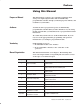
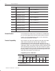
P–2 Using this Manual Chapter Title Topics Covered Appendix D Block Transfer Read and Write Configurations for 2 out/2 in Description of BTR/BTW words. Appendix E Block Transfer Read and Write Configurations for 2 out/6 in Description of BTR/BTW words. Appendix F Block Transfer Read and Write Configurations for 1 out/7 in Description of BTR/BTW words. Appendix G Block Transfer Read and Write Configurations for 3 out/5 in Description of BTR/BTW words.
Using this Manual P–3 You can place your analog module in any I/O module slot of the I/O chassis. Do not put the analog module in the same module group as a digital high density module unless you are using 1 or 1/2-slot addressing. Avoid placing the analog module close to ac modules or high voltage dc modules. Related Publications For a list of publications with information on Allen-Bradley programmable controller products, consult our publication index SD499.
P–4 Using this Manual Publication 1771ĆUM127B-EN-P - December 2002
Table of Contents Overview of the High Resolution Isolated Analog Modules Installing the Module Chapter 1 Chapter Objectives . . . . . . . . . . . . . . . . . . . . . . . . . . . . . . . . . . . Module Description . . . . . . . . . . . . . . . . . . . . . . . . . . . . . . . . . . . Features of the High Resolution Isolated Analog Series Modules . . . Catalog/Channel Numbers . . . . . . . . . . . . . . . . . . . . . . . . . . . . . .
toc-ii Table of Contents Configuring the Module Chapter 4 Chapter Objectives . . . . . . . . . . . . . . . . . . . . . . . . . . . . . . . . . . . Configuring the High Resolution Isolated Analog Modules . . . . . . . . Default Configurations . . . . . . . . . . . . . . . . . . . . . . . . . . . . . . . . . Module Level Programming Features . . . . . . . . . . . . . . . . . . . . . . Module Configuration" Verification . . . . . . . . . . . . . . . . . . . . . . . . Temperature Scale . . . . . . . . . . .
Table of Contents Module Status and Input Data Chapter 5 Chapter Objectives . . . . . . . . . . . . . . . . . . . . . . . . . . . . . . . . . . . Reading Data from the Module . . . . . . . . . . . . . . . . . . . . . . . . . . . Block Transfer Read Data Format . . . . . . . . . . . . . . . . . . . . . . . . . Outputs Only" Block Transfer Read Data Header . . . . . . . . . . . . . . Inputs Only" and Output/Input" Block Transfer Read Data Header . Input Status Data . . . . . . . . . . . . . . . . . . . .
toc-iv Table of Contents Block Transfer Write and Block Transfer Read Configurations for 8 Output/0 Input 1771ĆN Series Modules Appendix C Block Transfer Write and Block Transfer Read Configurations for 2 Output/2 Input 1771ĆN Series Modules Appendix D Block Transfer Write and Block Transfer Read Configurations for 2 Output/6 Input 1771ĆN Series Modules Block Transfer Write and Block Transfer Read Configurations for 1 Output/7 Input 1771ĆN Series Modules Block Transfer Write and Block Transfer Read
Table of Contents Block Transfer Write and Block Transfer Read Configurations for 4 Output/4 Input 1771ĆN Series Modules Block Transfer Write and Block Transfer Read Configurations for 6 Output/2 Input 1771ĆN Series Modules Block Transfer Write and Block Transfer Read Configurations for 5 Output/3 Input 1771ĆN Series Modules Block Transfer Write and Block Transfer Read Configurations for 7 Output/1 Input 1771ĆN Series Modules CSA Hazardous Location toc-v Appendix H What This Appendix Contains . . . .
toc-vi Table of Contents Publication 1771ĆUM127B-EN-P - December 2002
Chapter 1 Overview of the High Resolution Isolated Analog Modules Chapter Objectives This chapter gives you information on: • features of the input/output modules • how the modules communicate with programmable controllers Module Description The high resolution isolated analog modules are intelligent block transfer modules that interface analog signals with Allen-Bradley PLC-3 and PLC-5 family programmable controllers that have block transfer capability.
1–2 Overview of the High Resolution Isolated Analog Modules The modules have either four or eight channels, each electrically isolated from each other and from the backplane. Input and output terminations are made through prefabricated cables which connect to remote termination panels (RTP). The modules are compatible with all 1771-A1B, A2B, A3B, A3B1, A4B, and later 1771 universal I/O chassis. In addition, they can be used in 1771-AM1, and -AM2 chassis.
1–3 Overview of the High Resolution Isolated Analog Modules • RTD input channels – reportsoC, oF, or ohms for 100Ω platinum, 120Ω nickel, or • • • • • 10Ω copper sensors – reports ohms for other types of sensors – 0.1oC/0.
1–4 Overview of the High Resolution Isolated Analog Modules How the High Resolution Isolated Analog Modules Communicate with Processors The processor transfers data to and from the module using BTW (block transfer write) and BTR (block transfer read) instructions in your ladder diagram program. These instructions let the processor obtain input values and status from the module, and let you establish the module’s mode of operation (Figure NO TAG). 1.
Chapter 2 Installing the Module Chapter Objectives Before You Install Your Analog Module This chapter gives you information on: For information on See page Before You Install Your Module . . . . . . . . . . . . . . . . . . . . . . . Determining Power Requirements . . . . . . . . . . . . . . . . . . . . Determining Module Location in the Chassis . . . . . . . . . . . . . Installing the Module . . . . . . . . . . . . . . . . . . . . . . . . . . . . . . Connecting Wiring . . . . . . . . . . . . . . . . .
2–2 Installing the Module Add this value to the requirements of all other modules in the I/O chassis to prevent overloading the chassis backplane and/or backplane power supply. Determine Module Location in the I/O Chassis Place your module in any slot of the I/O chassis except for the extreme left slot. This slot is reserved for processors or adapter modules. Group your modules to minimize adverse affects from radiated electrical noise and heat. We recommend the following.
Installing the Module 2–3 Key the Backplane Connector Place your module in any slot in the chassis except the leftmost slot which is reserved for processors or adapters. Position the keying bands in the backplane connectors to correspond to the key slots on the module. Place the keying bands: between 26 and 28 between 32 and 34 I/O chassis Keying Bands You can change the position of these bands if subsequent system design and rewiring makes insertion of a different type of module necessary.
2–4 Installing the Module 1771ĆA1B, ĆA2B, ĆA3B, ĆA3B1, ĆA4B I/O chassis locking tab 1771ĆA1B, ĆA2B, ĆA3B1, ĆA4B Series B I/O chassis locking bar pin locking bar card guides card guides module Snap the chassis latch over the top of the module to secure it. module Swing the chassis locking bar down into place to secure the modules. Make sure the locking pins engage. 19809 3. Connect the 1771-NC cable to the module as shown in Figure 2.1. A. Slide the locking bar up. B.
Installing the Module Connecting Wiring 2–5 The N-series modules are cable-connected to a remote termination panel using cat. no. 1771-NC6 (6 ft) or -NC15 (15 ft) cables. Variations of remote termination panels are used, depending on the type of module used.
2–6 Installing the Module Figure 2.2 Mounting Dimensions for the Remote Termination Panels RTP1, RTP3, RTP4 B A Inches (Millimeters) 3.0 (75.0) J8 J7 J6 J5 J1 J2 J3 J4 2.3 (58.4) 5.30 (134.6) RT41, RT44 3.0 (75.0 ) J1 J2 J3 J4 2.3 (58.4) 2.3 (58.4) Dimensions to back of DIN rail 3.5 (88.9) 19366 Table 2.
2–7 Installing the Module Figure 2.3 Remote Termination Panel Wiring Module End of 1771ĆNC cable Example: Channel 1 Connections R1 = Return 1 I1 = Input 1 O1 = Output 1 S1 = Shield 1 Note: Terminals W1, W2 and W3 are spares. Do not use terminals CR and CL. RTP1 RTP End of 1771ĆNC cable DIN Rail Channel 1 Connections R1 = Return 1 I1 = Input 1 O1 = Output 1 S1 = Shield 1 Module End of 1771ĆNC cable Note: Terminals W1, W2 and W3 are spares. Do not use terminals CR and CL.
2–8 Installing the Module Field wiring to the remote termination panel is the same for all remote termination panel variations. Refer to Figure 2.4. Each channel has 4 connections: R, I, O, and S. • • • • R = return I = input O = output S = shield Channel 1 would use R1, I1, O1, and S1; channel 2 would use R2, I2, O2, and S2; and so on for the remaining channels. To connect field wiring to the remote termination panel: 1. Strip 3/8 inch (9.25 mm) of insulation from the 22-12 AWG wire. 2.
2–9 Installing the Module Connecting 4ĆWire Sensors Figure 2.5 shows how to connect 4-wire sensors to the remote termination panel. A 4-wire sensor has two pairs of leads; one pair for each resistor junction. One wire of the four is not used (it does not matter which one). This leaves three wires – one pair and one single wire. You must connect the single wire to the terminal marked “O_”. You connect the remaining pair of wires to terminals “I_” and “R_”.
2–10 Installing the Module Sourcing Input Analog Modules The 1771-NIS, 1771-NBSC and 1771-NB4S modules are sourcing/sinking input modules. These modules can supply the necessary loop power for 2-wire transmitters connected to the input. All loop power functionality is contained within the analog module. Examples of typical configurations are shown in Figure 2.6. No external resistors are required. Figure 2.
Installing the Module Making Your Own Cables 2–11 If you are not using thermocouples, you can terminate the analog module to a terminal block by cutting the 25-pin RTP end connector off the standard cable and wiring to your terminal block. Refer to Table 2.B for wire termination designations. Table 2.
2–12 Installing the Module Grounding the Field Devices When using shielded cable or shielded thermocouple extension wire, ground the foil shield and drain wire only at one end of the cable. We recommend that you wrap the foil shield and drain wire together and connect them to the “S” connection on the RTP for the particular channel. All shield connections are internally connected together in the RTP so that only one wire is required to ground the entire remote termination panel.
2–13 Installing the Module Interpreting the Indicator Lights The front panel of the analog module contains two bi-color indicators: a red/green RUN/FLT (fault) indicator and a red/green CAL/COM indicator (Figure 2.8). Figure 2.8 Diagnostic Indicators RUN/FLT CAL/COM Run/Fault indicator. This indicator will flash green until the first valid block transfer write has been received. If a fault is found initially or occurs later, the RUN/FLT indicator turns red. Calibrate/communication indicator.
2–14 Installing the Module Publication 1771ĆUM127B-EN-P - December 2002
Chapter 3 Communicating With Your Analog Module Chapter Objectives In this chapter, we describe • block transfer programming • quick-startup sample programs for the PLC-3 and PLC-5 processors • module scan time issues Block Transfer Programming Your module communicates with the processor through bidirectional block transfers. This is the sequential operation of both read and write block transfer instructions.
3–2 Communicating With Your Analog Module Your analog module works with a default configuration upon powerup as long as a block transfer write (BTW) has not been initiated. See the configuration default section in chapter 4 to understand what this configuration looks like. Refer to the sample programs in this chapter to get started. Your program should monitor status bits (such as overrange, underrange, alarms, etc.) and block transfer read activity.
3–3 Communicating With Your Analog Module Figure 3.1 PLCĆ3 Family Sample Program Structure Program Action At powerup, the user program enables a block transfer read. Then it initiates a block transfer write to configure module. Thereafter, the program continuously perĆ forms read and write block transfers.
3–4 Communicating With Your Analog Module Module Scan Time Scan time is defined as the amount of time it takes for the module to read the input channels and place new data into the data buffer and/or read the data buffer and write new data to the output channels. Scan time for your module is shown in Figure 3.3. Figure 3.
3–5 Communicating With Your Analog Module The differences between the types of 1771-N series modules is related to the number of output channels each module has. A module with only inputs (no outputs) requires one BTW after powerup. Thereafter, it sends back input data and module status by way of BTRs. A module with outputs requires BTWs to configure it and update its output data. BTRs are required to send back input data and module status.
3–6 Communicating With Your Analog Module Modules without output channels do not require rungs 2 and 3. Instead, move the input condition instructions from rung 2 to the front of rung 4, and specify the BTW length equal to 59. Sample Ladder Diagram Ć PLCĆ5 Family Processors The following PLC-5 program is very similar to the preceding PLC-3 program with the following exceptions: • You use enable bits instead of done bits as the conditions on each rung.
3–7 Communicating With Your Analog Module Setting Up the Data Table File If you use a 1771-NBTC module with the parameters listed below, the PLC-5 data table file screen on an industrial terminal screen would look similar to Figure 3.6.
3–8 Communicating With Your Analog Module Figure 3.
Chapter 4 Configuring the Module Chapter Objectives In this chapter you will read how to: • configure your module’s features • condition your inputs and outputs and • enter your data. Configuring the High Resolution Isolated Analog Modules Because of the many analog devices available and the wide variety of possible configurations, you must configure your module to conform to the analog device and specific application that you have chosen.
4–2 Configuring the Module When making entries in the configuration block, use binary or hexadecimal only. Default Configurations The modules can be operated in a default mode by using zeroes in all but the first word of the BTW data file. The first word must identify the number of outputs on the module. For example, the first word for the 8 output module (cat. no. 1771-NOC) would be 8880 hexadecimal; the first word for the 2 out/6 input module (cat. no.
Configuring the Module Module Level Programming Features 4–3 Module level programming features include: • • • • module “configuration” verification temperature scale data format real time sample Module Configuration" Verification The verify bit 00 in the block transfer write word 3 allows you to compare the configuration information the module is using to the configuration information contained in a block transfer write (BTW).
4–4 Configuring the Module The 1771-N series modules use 15-bit signed magnitude BCD. The maximum range value available then becomes7999. + Figure 4.1 4ĆDigit Binary Coded Decimal Sign Bit Ć 0 = + 1 X 22 = 4 1 X 21 = 2 7 1=Ć 1 X 20 = 1 1 X 23 = 8 0 X 22 = 0 0 X 21 = 0 9 1 X 20 = 1 1 X 23 = 8 0 X 22 = 0 0 X 21 = 0 9 1 X 20 = 1 1 X 23 = 8 0 X 22 = 0 0 X 21 = 0 910 1 X 20 = 1 0 Sign Bit 1 1 1 1 0 0 1 1 9 7 0 0 1 1 0 9 9 Table 4.
Configuring the Module 4–5 Two's Complement Binary Two’s complement binary is used with PLC-3 processors when performing mathematical calculations internal to the processor. To complement a number means to change it to a negative number. For example, the following binary number is equal to decimal 22. 101102 = 2210 First, the two’s complement method places an extra bit (sign bit) in the left-most position, and lets this bit determine whether the number is positive or negative.
4–6 Configuring the Module In the RTS mode, the module scans and updates its inputs at a user defined time interval ∆( T) instead of the default interval. The module ignores block transfer read (BTR) requests for data until the sample time period elapses. The BTR of a particular data set occurs only once at the end of the sample period and subsequent requests for transferred data are ignored by the module until a new data set is available.
Configuring the Module Channel Type Sensor Low Scaling Point High Scaling Point 10V Output Ć10.0V +10.0V 25mA Output 4mA 20mA 50mA Output 1mA 50mA 5V Input 1.0V 5.0V 10V Input Ć10.0V +10.0V 4Ć20mA Input 4mA 20mA Millivolt Ć5mV +55mV Temperature Ć300C/Ć508F 1800C/3272F Millivolt Ć100mV +100mV Temperature Ć300C/Ć508F 1800C/3272F Resistance 1.
4–8 Configuring the Module If both the low scale and high scale values are set to 0, the module reports data in the default resolution as shown below. Channel Type 10V Output 25mA Output 50mA Output 5V Input 10V Input 4 20mA Input 4Ć20mA Ć5/+55mV 5/+55mV Input 100mV Input 650 Ohm Input Publication 1771ĆUM127B-EN-P - December 2002 Data Format Temperature Scale Resolution Binary N/A 0.1mV/count BCD N/A 1mV/count Binary N/A 0.1mA BCD N/A 1mA Binary N/A 0.
Configuring the Module 4–9 Clamping Output channels can be configured to limit or clamp the output signal at a specified value regardless of the output data value written to the module. Low and high clamping values are written to the module in scaled units, and must be within the absolute signal limits shown below. Output Type Low Absolute Limit High Absolute Limit + 10V Ć10.4V 10.
4–10 Configuring the Module Ramping Output ramping is used to limit the rate of change of an output channel. You enter the rate as a percentage (between 0 and 200%) of full scale per second, where 0 disables the ramping feature, and full scale is the difference between the low and high scaling points. 4.3 shows the effect of ramping on the output signal. Figure 4.
Configuring the Module 4–11 Reset Value If the channel is programmed to go to a user-selectable reset value upon I/O reset, the value is entered (in scaled units) into that channel’s proper configuration word. The value entered must be between the high and low absolute limits. If user-selectable resetting is not chosen, this field should be set to 0.
4–12 Configuring the Module • Overrange - This bit is set if the input rises above the maximum range for that specific input type. This alarm is predefined and cannot be changed by the user. For all voltage, RTD and thermocouple inputs, this bit indicates an open channel. Alarm Deadband Alarm deadband allows the user to program a hysteresis effect on the alarming for a given channel.
Configuring the Module 4–13 Rate Alarm This bit is set when the input changes at a rate faster than the user-defined value. Rate of change values can range from 0.05% to 50% of the input’s full scale range per second. Full scale range is defined as the difference between the high scale value and the low scale value. The rate is specified in scaled units per second. Figure 4.
4–14 Configuring the Module Figure 4.7 Digital Filter Lag Equation Illustration 100% 63% Amplitude 0 Unfiltered Input TA = 0.01 sec TA = 0.5 sec TA = 0.99 sec 0 0.01 0.5 0.99 Time in Seconds Thermocouple Type This field lets you select the type of sensor connected to a thermocouple input channel. This field must be 0 for all other channel types.
4–15 Configuring the Module RTD Type This field lets you select the type of sensor connected to a 650 ohm input channel. This field must be 0 for all other channel types. Sensor Type Binary Value Decimal 10 09 08 Octal 12 11 10 Resistance 0 0 0 100 Ohm Pt. European Std. 0 0 1 100 Ohm Pt. U.S. Std. 0 1 0 10 Ohm Copper 0 1 1 120 Ohm Nickel 1 0 0 10 Ohm Offset This field lets you compensate for a small offset error in a 10 ohm copper RTD. Values can range from -0.99 to +0.
4–16 Configuring the Module Bit/Word Description of Word 0 Word Bit Definition Word 0 00Ć03 Constant = 0 Bits 04Ć07 Number of outputs = 0010 Bits 10Ć15 Constant = 00 1000 Bits 16Ć17 Block transfer write type = 10 The next group of words sets the outputs of the module, if the module has outputs. For example, if this is a 2 output/6 input module, words 1 and 2 would contain the data for the two output channels. If the module has four outputs, words 1 thru 4 would contain output channel data.
4–17 Configuring the Module Bit/Word Description of Output Configuration Words 3 and 4 Word Decimal Bit (Octal Bit) Definition Bit 00 Verify. If this bit is set to 1, the module will compare its current programming with the programming downloaded in the BTW. If they are the same, it will verify good; if they are different, the module will verify bad. In no case will any programming data in the BTW be applied to the module. Bit 01 Temperature scale.
4–18 Configuring the Module Bit/Word Description of Output Configuration Words 5 through 10 Word Decimal Bit (Octal Bit) Word 5 Bits 00Ć15 (00Ć17) Low scale value for channel 1. Scale values are limited to +32767 in binary format; +7999 in BCD format. Word 6 Bits 00Ć15 (00Ć17) High scale value for channel 1. Scale values are limited to +32767 in binary format; +7999 in BCD format. Word 7 Bits 00Ć15 (00Ć17) Low clamp value for channel 1.
4–19 Configuring the Module The following six words configure the first input channel of the module. These words are repeated as necessary for each input in the module. For example, if this is a 2 output/6 input module, words 1 through 4 would configure the module, words 5 through 16 would configure the 2 output channels (six words each). Then six groups of seven words each (one group for each input channel) would configure the module’s six input channels. Input Programming Word/Dec.
4–20 Configuring the Module Word Word 23 Decimal Bit (Octal Bit) Definition Bits 8Ć15 (10Ć17) Filter time constant. Specifies the time constant of a digital, first order lag filter on the input in 0.1 second units. Legal values are 0.1 to 10.0 seconds (binary) or 0.1 to 9.9 (BCD). A value of 0 disables the filter. Bits 00Ć07 10 ohm offset. Compensates for a resistance offset on a 10 ohm copper RTD. Range of +0.99 ohms, in units of 0.01 ohms. This field must be 0 for all other RTDs.
Chapter 5 Module Status and Input Data Chapter Objectives In this chapter you will read about: • reading data from your module • block transfer read data format Reading Data from the Module Block transfer read (BTR) programming moves status and data from the module to the processor’s data table in one I/O scan. The processor user program initiates the request to transfer data from the module to the processor. The transferred words contain module status, channel status and input data from the module.
5–2 Module Status and Input Data Block Transfer Read Data Format The block transfer read data format consists of an initial block header which identifies the type of module (input, output, or output/input), and groups of words that contain information on either an input channel or an output channel. Output channel words are configured immediately after the block header. If the module contains both output and input channels, the output channel words come first in the block transfer read data format.
5–3 Module Status and Input Data Word Decimal Bit (Octal Bit) Definition Bit 13 (15) Module alarm. This bit is set if there is an alarm bit set for one or more channels. The input alarm bits are low, high alarm and rate alarm. The output channel alarm bits are low and high clamp, and the rate limit alarm. Bit 14 (16) Bad channel data. This bit is set if the module is in BCD mode and one or more of the input data values sent in the last BTW are not legal BCD values. Bit 15 (17) Powerup bit.
5–4 Module Status and Input Data Word Decimal Bit (Octal Bit) Definition Bit 08 (10) Module fault. This bit is set if any of the programming data sent to the module in the most recent BTW was illegal, or if one or more channels has the bad calibration bit set. Bits 09Ć10 (11Ć12) Program verify. Indicates the result of verify request. 00 = verify not requested; 10 = verify failed; 11 = verify succeeded Bit 11 (13) I/O reset. This bit is set whenever the I/O reset line on the backplane is asserted.
5–5 Module Status and Input Data The above two words would be repeated for each input channel. For example, if this module had two input channels, the following words would be used. Word/Dec.
5–6 Module Status and Input Data Output Status Data Each output channel also has two words associated with it. The first word contains low and high clamp, rate alarm, bad data, bad program and bad calibration information for the processor. This is followed by raw count data for that channel. If the module contains both input and output channels, the output channel words would immediately follow the header words. Word/Dec.
Module Status and Input Data 5–7 Bit/Word Description for Output Status Data Words Word Decimal Bit (Octal Bit) Bit 00-03 Word 4 Word 5 Definition Not used. Always 0 Bit 04 Low clamp. This bit is set if alarms are enabled and the output data is lower than the low clamp value. Bit 05 High clamp. This bit is set if alarms are enabled and the output data is higher than the high clamp value. Bit 06 Rate alarm.
5–8 Module Status and Input Data Publication 1771ĆUM127B-EN-P - December 2002
Chapter 6 Module Calibration Chapter Objective In this chapter we tell you how to calibrate your module. Your module is shipped from the factory already calibrated. This chapter tells you how to recalibrate or change calibration. Tools and Equipment In order to calibrate your analog module you will need the following tools and equipment: Tool or Equipment Precision Voltage Source Description 0-10V, 1µV resolution High Precision Resistors: 649 ohm, 0.01%, 5ppm/oC 1 ohm, 0.
6–2 Module Calibration Table 6.A Resistor Tolerance vs. Expected Error Resistor Tolerance Expected Error 0.1% 0.1% 0.5% 0.5% 1.0% 1.0% Note: If the tolerance error of the 649 ohm resistor is > than +18 ohms (2.8%), calibration will fail. Table 6.B Temperature Coefficient Error Temperature Coefficient of Resistor 25ppm/oC 50ppm/oC 200ppm/oC nT (Calibration temperature deviation from 25oC) Expected Error 5 oC 0.081 ohms (0.012%) 10oC 0.162 ohms (0.025%) 20oC 0.325 ohms (0.05%) 5 oC 0.
6–3 Module Calibration • manual calibration – refer to the procedure below. • 6200 I/O CONFIG software – refer to your 6200 software publications (release 4.2 or later) for procedures for calibrating. • PCO operator interface software – refer to your 6190-PCO software publications for procedures for calibrating. Indicator Operation During Calibration During calibration, the RUN/FLT indicator will turn to green. The CAL/COM indicator will turn to flashing red.
6–4 Module Calibration Word/Dec.
6–5 Module Calibration Figure 6.1 Connecting a Resistor or Decade Resistance Box to the Remote Termination Panel Connect the resistor across terminals R1-I1 and O1. 640 ohm resistor for high reference value. 1 ohm resistor for low reference value. Decade resisĆ tance box If using a decade resistance box, connect in place of the resistor 12935-I 3. Send a block transfer write to the module with word 1 containing CAL CLK bit (01) = 1, and HI/LO bit (00) = 0. 4.
6–6 Module Calibration Table 6.E Calibration Block Transfer Read Word/Dec.
Module Calibration 6–7 Output Channel Calibration 1. Set the appropriate bit in the BTW output calibration mask (word 3); channel 1 is bit 0, channel 2 is bit 01, etc. If calibrating only one channel, set the appropriate bit. If calibrating the entire module (all outputs), set all bits (00 through 07). 2. Send a block transfer write to the module with word 1 containing CAL CLK bit (01) = 1, and HI/LO bit (00) = 0 and all output cal values = 0. 3.
6–8 Module Calibration 8. Enter the first set of calculated low and high values into the first channel output cal values of the block transfer write calibration data file. If you are calibrating more than one output channel simultaneously, enter the output cal values from the lowest numbered output channel in the first output cal value slots. The next lowest channel in the output mask goes in the second slot of output cal values, and so on. 9.
Chapter 7 Troubleshooting Chapter Objective We describe how to troubleshoot your module by observing indicators and by monitoring status bits reported to the processor. Diagnostics Reported by the Module At power-up, the module turns the RUN/FLT indicator to red, then checks for: • correct RAM operation • EPROM operation • EEPROM operation After passing initial diagnostics, the module turns the RUN/FLT indicator to flashing green.
7–2 Troubleshooting Troubleshooting with the Indicators Table 7.A shows indications, probable causes and recommended actions to correct common faults which may occur. Table 7.A Troubleshooting Chart Indication Probable Cause No power to module Both indicators are OFF Recommended Action Check power to I/O chassis. Recycle as necessary.
Troubleshooting 7–3 Table 7.B Module Status Reported in BTR Word 1 Decimal Bit (Octal Bit) Word 1 Word 2 Bit 00Ć05 Explanation Not used Bit 06 Bad structure. This bit is set if there is an error in the BTW header. Bit 07 Bad program. This bit is set if any of the module level programming data is illegal. Bit 08 (10) Module fault. This bit is set if any of the programming data sent to the module in the most recent BTW was illegal, or if one or more channels has the bad calibration bit set.
7–4 Troubleshooting Table 7.C Output Channel Status Word (1 per output channel) Decimal Bit (Octal Bit) Definition Bit 04 Low clamp. This bit is set if alarms are enabled and the output data is lower than the low clamp value. Bit 05 High clamp. This bit is set if alarms are enabled and the output data is higher than the high clamp value. Bit 06 Rate alarm. This bit is set if alarms are enabled and the output data changed faster than the programmed ramp rate. Bit 07 Bad data.
Appendix A Specifications General Specifications Number of Channels (depends on specific module) 8 individually isolated, or 4 individually isolated I/O Chassis Location any single I/O module slot A/D Resolution 16 bits or 15 bits plus sign bit D/A Resolution 14 bits or 13 bits plus sign bit Input Filtering 6 pole, low pass hardware filter Calibration Interval 1 year Isolation Voltage Designed to withstand 1000V dc continuous between input and output channels and between input and backplane c
A–2 Specifications Vibration IEC 60068-2-6 (Test Fc, Operating) 2g @ 10-500Hz ESD Immunity IEC 61000-4-2 4kV contact discharges Radiated RF Immunity IEC 61000-4-3 10V/m with 1kHz sine-wave 80% AM from 30MHz to 1000MHz 10V/m with 200Hz 50% Pulse 100% AM at 900MHz EFT/B Immunity IEC 61000-4-4 +1kV @ 5kHz on signal ports Surge Transient Immunity IEC 61000-4-5 +2kV line-earth (CM) on shielded ports Conducted RF Immunity IEC 61000-4-6 10V rms with 1kHz sine wave 80% AM from 150kHz to 30MHz Emissions
Specifications A–3 Temperature Specifications Input Range (selectable) ±100mV Thermocouple Input -5 to +55mV Thermocouple Input 1Ć650Ω RTD Input ±105mV -5.5 to 56.
A–4 Specifications Temperature Resolution of Thermocouple Inputs +100mV/Thermocouple Inputs 0.60 0.55 0.50 Resolution (° C/bit) 0.45 0.40 0.35 0.30 0.25 0.20 0.15 0.10 0.05 0.00 -200 0 200 400 600 800 1000 1200 1400 1600 1800 1832 2192 2552 2912 3272 Temperature (°C) 0.80 0.70 Resolution ( F/bit) 0.60 ° 0.50 0.40 0.30 0.20 0.10 0.
Specifications A–5 -5/+55mV/Thermocouple Inputs 0.20 Resolution (° C/bit) 0.15 0.10 0.05 0.00 -500 0.032 °C Display Resolution Limit -300 -100 100 300 500 700 900 1100 1300 Temperature (°C) 1500 1700 1900 2100 2300 2500 0.25 Resolution ( F/bit) 0.20 0.15 ° 0.10 0.06 °F Display Resolution Limit 0.05 0.
A–6 Specifications ±5V Inputs ±10V Inputs 4Ć20mA Sourcing Input Input Range +5.5V (±22mA with resistor) +10.5V (±42mA with resistor) 0.1Ć21.0mA Input Resolution 168µV/bit (0.
Specifications A–7 Figure A.2 Derating Curves for 50mA Outputs on the 1771ĆN Series Modules Output Current vs. Ambient Temperature as a function of Load Resistance 50 40 Output Current (mA) 30 20 10 0 0 10 20 30 40 Ambient Temperature 50 60 (oC) Important: If you require 60oC operation with 50mA outputs, install a resistance in series with the load impedance so that the total load impedance is equal to 300 ohms.
A–8 Specifications Publication 1771ĆUM127B-EN-P - December 2002
B Appendix Block Transfer Write and Block Transfer Read Configurations for 0 Output/8 Input 1771ĆN Series Modules What This Appendix Contains This appendix contains block transfer write and block transfer read configurations and bit/word descriptions for 1771-N series modules with no outputs and eight inputs. Block Transfer Write Configuration Block for 8 Input Modules Word/Dec.
B–2 Block Transfer Write and Block Transfer Read Configurations for 0 Output/8 Input 1771-N Series Modules Word/Dec. Bit 15 14 13 12 11 10 09 08 07 06 05 04 03 02 01 00 Word/Octal Bit 17 16 15 14 13 12 11 10 07 06 05 04 03 02 01 00 19 Low Alarm Value 20 High Alarm Value 21 Alarm enable 22 23 Rate Alarm: Scaled Units per second Filter Time Constant: 0.1 second units Thermocouple Type 0 Alarm Deadband RTD Type 10 Ohm Offset; 0.
Block Transfer Write and Block Transfer Read Configurations for 0 Output/8 Input 1771-N Series Modules B–3 Word/Dec. Bit 15 14 13 12 11 10 09 08 07 06 05 04 03 02 01 00 Word/Octal Bit 17 16 15 14 13 12 11 10 07 06 05 04 03 02 01 00 Channel 7 Programming 45 Low Scale Value 46 High Scale Value 47 Low Alarm Value 48 High Alarm Value 49 Alarm enable 50 51 Rate Alarm: Scaled Units per second Filter Time Constant: 0.
B–4 Block Transfer Write and Block Transfer Read Configurations for 0 Output/8 Input 1771-N Series Modules Word Decimal Bit (Octal Bit) Bits 03-14 (03-16) Not used. Always 0 Bit 15 (17) CJ alarm enable. A value of 1 enables over and underrange indication for the cold junction channel. If the module does not have a cold junction channel, this bit is 0. Word 2 Bits 00-15 (00-17) Real time sample. Sample time in milliseconds. 0 = off. RTS minimum is 100msec (counts = 100).
Block Transfer Write and Block Transfer Read Configurations for 0 Output/8 Input 1771-N Series Modules Decimal Bit (Octal Bit) Word Definition Thermocouple type. Specifies type of TC linearization on TC channels. 0000 = millivolts; 0001 = B; 0010 = E; 0011 = J; 0100 = K; 0101 = R; 0110 = S; 0111 = T; 1000 = C (1771ĆNT2 only); 1001 = N (1771ĆNT2 only). This field must be 0 for non-thermocouple channels. Bits 12-15 (14-17) Word 9 continued B–5 Words 10 thru 16 Same as words 3 thru 9 but for channel 2.
B–6 Block Transfer Write and Block Transfer Read Configurations for 0 Output/8 Input 1771-N Series Modules Word/Dec.
Block Transfer Write and Block Transfer Read Configurations for 0 Output/8 Input 1771-N Series Modules B–7 Block Transfer Read Bit/Word Descriptions for 8 Input Modules Word Decimal Bit (Octal Bit) Word 0 Bits 00-15 (00-17) Always = 8800 hexadecimal Bits 00-05 Not used Word 1 Word 2 Word 3 Definition Bit 06 Bad structure. This bit is set if there is an error in the BTW header. Bit 07 Bad program. This bit is set if any of the module level programming data is illegal.
B–8 Block Transfer Write and Block Transfer Read Configurations for 0 Output/8 Input 1771-N Series Modules Word Word 4 continued Word 5 Decimal Bit (Octal Bit) Definition Bit 04 Low alarm. This bit is set if alarms are enabled and the input data is lower than the low alarm setpoint. Bit 05 High alarm. This bit is set if alarms are enabled and the input data is higher than the high alarm setpoint. Bit 06 Rate alarm.
C Appendix Block Transfer Write and Block Transfer Read Configurations for 8 Output/0 Input 1771ĆN Series Modules What This Appendix Contains This appendix contains block transfer write and block transfer read configurations and bit/word descriptions for 1771-N series modules with eight outputs and no inputs. Block Transfer Write Configuration Block for 8 Output Modules Word/Dec.
C–2 Block Transfer Write and Block Transfer Read Configurations for 8 Output/0 Input 1771-N Series Modules Word/Dec.
Block Transfer Write and Block Transfer Read Configurations for 8 Output/0 Input 1771-N Series Modules C–3 Word/Dec.
C–4 Block Transfer Write and Block Transfer Read Configurations for 8 Output/0 Input 1771-N Series Modules Word Word 9 Bit Definition Bit 00 Verify. If this bit is set to 1, the module will compare its current programming with the programming downloaded in the BTW. If they are the same, it will verify good; if they are different, the module will verify bad. In no case will any programming data in the BTW be applied to the module. Bit 01 Temperature scale.
C–5 Block Transfer Write and Block Transfer Read Configurations for 8 Output/0 Input 1771-N Series Modules Word Bit Definition Words 41 thru 46 Same as words 11 thru 16 but for channel 6. Words 47 thru 52 Same as words 11 thru 16 but for channel 7. Words 53 thru 58 Same as words 11 thru 16 but for channel 8. Block Transfer Read Word Assignments for 8 Output Modules Word/Dec.
C–6 Block Transfer Write and Block Transfer Read Configurations for 8 Output/0 Input 1771-N Series Modules Word/Dec.
Block Transfer Write and Block Transfer Read Configurations for 8 Output/0 Input 1771-N Series Modules Word Word 5 Decimal Bit (Octal Bit) C–7 Definition Bit 06 Rate alarm. This bit is set if alarms are enabled and the output data changed faster than the programmed ramp rate. Bit 07 Bad data. This bit is set if BCD format was chosen and the output data is not a legal BCD value. Bits 08 (10) Bad programming.
C–8 Block Transfer Write and Block Transfer Read Configurations for 8 Output/0 Input 1771-N Series Modules Publication 1771ĆUM127B-EN-P - December 2002
D Appendix Block Transfer Write and Block Transfer Read Configurations for 2 Output/2 Input 1771ĆN Series Modules What This Appendix Contains This appendix contains block transfer write and block transfer read configurations and bit/word descriptions for 1771-N series modules with two outputs and two inputs. Block Transfer Write Configuration Block for the 2 Output/2 Input Modules Word/Dec.
D–2 Block Transfer Write and Block Transfer Read Configurations for 2 Output/2 Input 1771-N Series Modules Word/Dec. Bit 15 14 13 12 11 10 09 08 07 06 05 04 03 02 01 00 Word/Octal Bit 17 16 15 14 13 12 11 10 07 06 05 04 03 02 01 00 18 High Scale Value 19 Low Alarm Value 20 High Alarm Value 21 Alarm enable 22 23 Rate Alarm: Scaled Units per second Filter Time Constant: 0.1 second units Thermocouple Type 0 Alarm Deadband RTD Type 10 Ohm Offset: 0.
Block Transfer Write and Block Transfer Read Configurations for 2 Output/2 Input 1771-N Series Modules Word Word 3 D–3 Decimal Bit (Octal Bit) Definition Bit 00 Verify. If this bit is set to 1, the module will compare its current programming with the programming downloaded in the BTW. If they are the same, it will verify good; if they are different, the module will verify bad. In no case will any programming data in the BTW be applied to the module. Bit 01 Temperature scale.
D–4 Block Transfer Write and Block Transfer Read Configurations for 2 Output/2 Input 1771-N Series Modules Word Decimal Bit (Octal Bit) Word 18 Bits 00-15 (00-17) High scale value for channel 3. Word 19 Bits 00-15 (00-17) Low alarm value for channel 3. Word 20 Bits 00-15 (00-17) High alarm value for channel 3. Word 21 Bits 00-14 (00-16) Rate alarm. If the channel's input changes at a rate faster than this value and the alarm enable bit is set, the channel will indicate a rate alarm condition.
D–5 Block Transfer Write and Block Transfer Read Configurations for 2 Output/2 Input 1771-N Series Modules Block Transfer Read Word Assignments for 2 Output/2 Input Module Word/Dec. Bit 15 14 13 12 11 10 09 08 07 06 05 04 03 02 01 00 Word/Octal Bit 17 16 15 14 13 12 11 10 07 06 05 04 03 02 01 00 0 Constant = 8800 Hexadecimal 1 Power up 2 1 3 Bad Chan.
D–6 Block Transfer Write and Block Transfer Read Configurations for 2 Output/2 Input 1771-N Series Modules Block Transfer Read Bit/Word Description for 2 Output/2 Input Module Word Decimal Bit (Octal Bit) Word 0 Bits 00-15 (00-17) Always = 8800 hexadecimal Bits 00-05 Not used. Always 0 Word 1 Word 2 Word 3 Word 4 Publication 1771ĆUM127B-EN-P - December 2002 Definition Bit 06 Bad structure. This bit is set if there is an error in the BTW header. Bit 07 Bad program.
Block Transfer Write and Block Transfer Read Configurations for 2 Output/2 Input 1771-N Series Modules Word Decimal Bit (Octal Bit) Definition Bit 05 High clamp. This bit is set if alarms are enabled and the output data is higher than the high clamp value Bit 06 Rate alarm. This bit is set if alarms are enabled and the output data changed faster than the programmed ramp rate. Bit 07 Bad data. This bit is set if BCD data format was chosen and output value was not a legal BCD value.
D–8 Block Transfer Write and Block Transfer Read Configurations for 2 Output/2 Input 1771-N Series Modules Word Decimal Bit (Octal Bit) Definition Words 10 and 11 Same as words 8 and 9 but for channel 4.
E Appendix Block Transfer Write and Block Transfer Read Configurations for 2 Output/6 Input 1771ĆN Series Modules What This Appendix Contains This appendix contains block transfer write and block transfer read configurations and bit/word descriptions for 1771-N series modules with two outputs and six inputs. Block Transfer Write Configuration Block for 2 Output/6 Input Modules Word/Dec.
E–2 Block Transfer Write and Block Transfer Read Configurations for 2 Output/6 Input 1771-N Series Modules Word/Dec. Bit 15 14 13 12 11 10 09 08 07 06 05 04 03 02 01 00 Word/Octal Bit 17 16 15 14 13 12 11 10 07 06 05 04 03 02 01 00 18 High Scale Value 19 Low Alarm Value 20 High Alarm Value 21 Alarm enable 22 23 Rate Alarm: Scaled Units per second Filter Time Constant: 0.1 second units Thermocouple Type 0 Alarm Deadband RTD Type 10 Ohm Offset: 0.
Block Transfer Write and Block Transfer Read Configurations for 2 Output/6 Input 1771-N Series Modules E–3 Word/Dec. Bit 15 14 13 12 11 10 09 08 07 06 05 04 03 02 01 00 Word/Octal Bit 17 16 15 14 13 12 11 10 07 06 05 04 03 02 01 00 49 Alarm enable 50 51 Rate Alarm: Scaled Units per second Filter Time Constant: 0.1 second units Thermocouple Type 0 Alarm Deadband RTD Type 10 Ohm Offset: 0.
E–4 Block Transfer Write and Block Transfer Read Configurations for 2 Output/6 Input 1771-N Series Modules Decimal Bit (Octal Bit) Definition Bit 15 (17) CJ alarm enable. A value of 1 enables over and underrange indication for the cold junction channel. If the module does not have a cold junction channel, this bit is 0. Word 4 Bits 00-15 (00-17) Real time sample. Sample time in milliseconds. 0 = off. RTS minimum is 100msec (counts = 100). Maximum 10 seconds in binary; 9.999 seconds in BCD.
Block Transfer Write and Block Transfer Read Configurations for 2 Output/6 Input 1771-N Series Modules Word Word 22 Word 23 E–5 Decimal Bit (Octal Bit) Definition Bit 15 (17) Alarm enable bit. If set to 1, the module will report high alarm, low alarm, underrange, overrange, and rate alarm conditions. If 0, these warnings are suppressed. Bits 00-07 Alarm deadband. This field creates a hysteresis effect on the low and high alarms.
E–6 Block Transfer Write and Block Transfer Read Configurations for 2 Output/6 Input 1771-N Series Modules Block Transfer Read Word Assignments for 2 Output/6 Input Modules Word/Dec. Bit 15 14 13 12 11 10 09 08 07 06 05 04 03 02 01 00 Word/Octal Bit 17 16 15 14 13 12 11 10 07 06 05 04 03 02 01 00 0 Constant = 8800 Hexadecimal 1 Power up 2 1 Bad Chan.
Block Transfer Write and Block Transfer Read Configurations for 2 Output/6 Input 1771-N Series Modules E–7 Block Transfer Read Bit/Word Description for 2 Output/6 Input Modules Word Decimal Bit (Octal Bit) Word 0 Bits 00-15 (00-17) Always = 8800 hexadecimal Bits 00-05 Not used. Always 0 Word 1 Word 2 Word 3 Word 4 Definition Bit 06 Bad structure. This bit is set if there is an error in the BTW header. Bit 07 Bad program.
E–8 Block Transfer Write and Block Transfer Read Configurations for 2 Output/6 Input 1771-N Series Modules Word Word 4 continued Decimal Bit (Octal Bit) Bit 06 Rate alarm. This bit is set if alarms are enabled and the output data changed faster than the programmed ramp rate. Bit 07 Bad data. This bit is set if BCD data format was chosen and output value was not a legal BCD value. Bits 08 (10) Bad programming.
Block Transfer Write and Block Transfer Read Configurations for 2 Output/6 Input 1771-N Series Modules Word Decimal Bit (Octal Bit) E–9 Definition Words 16 and 17 Same as words 8 and 9 but for channel 7. Words 18 and 19 Same as words 8 and 9 but for channel 8.
E–10 Block Transfer Write and Block Transfer Read Configurations for 2 Output/6 Input 1771-N Series Modules Publication 1771ĆUM127B-EN-P - December 2002
Appendix F Block Transfer Write and Block Transfer Read Configurations for 1 Output/7 Input 1771ĆN Series Modules What This Appendix Contains This appendix contains block transfer write and block transfer read configurations and bit/word descriptions for 1771-N series modules with one output and seven inputs. Block Transfer Write Configuration Block for 1 Output/7 Input Modules Word/Dec.
F–2 Block Transfer Write and Block Transfer Read Configurations for 1 Output/7 Input 1771-N Series Modules Word/Dec. Bit 15 14 13 12 11 10 09 08 07 06 05 04 03 02 01 00 Word/Octal Bit 17 16 15 14 13 12 11 10 07 06 05 04 03 02 01 00 19 Low Alarm Value 20 High Alarm Value 21 Alarm enable 22 23 Rate Alarm: Scaled Units per second Filter Time Constant: 0.1 second units Thermocouple Type 0 Alarm Deadband RTD Type 10 Ohm Offset: 0.
Block Transfer Write and Block Transfer Read Configurations for 1 Output/7 Input 1771-N Series Modules F–3 Word/Dec. Bit 15 14 13 12 11 10 09 08 07 06 05 04 03 02 01 00 Word/Octal Bit 17 16 15 14 13 12 11 10 07 06 05 04 03 02 01 00 49 Alarm enable 50 51 Rate Alarm: Scaled Units per second Filter Time Constant: 0.1 second units Thermocouple Type 0 Alarm Deadband RTD Type 10 Ohm Offset: 0.
F–4 Block Transfer Write and Block Transfer Read Configurations for 1 Output/7 Input 1771-N Series Modules Word Decimal Bit (Octal Bit) Word 3 Bits 00-15 (00-17) Real time sample. Sample time in milliseconds. 0 = off. RTS minimum is 100msec (counts = 100). Maximum 10 seconds in binary; 9.999 seconds in BCD. Word 4 Bits 00-15 (00-17) Low scale value for channel 1. Scale values are limited to +32767 in binary format; +7999 in BCD format. Word 5 Bits 00-15 (00-17) High scale value for channel 1.
Block Transfer Write and Block Transfer Read Configurations for 1 Output/7 Input 1771-N Series Modules Word Word 15 Word 16 F–5 Decimal Bit (Octal Bit) Definition Bits 00-07 Alarm deadband. This field creates a hysteresis effect on the low and high alarms. For an alarm condition to be removed, the input signal must go above the low alarm limit or below the high alarm limit by an amount equal to the specified deadband.
F–6 Block Transfer Write and Block Transfer Read Configurations for 1 Output/7 Input 1771-N Series Modules Block Transfer Read Word Assignments for 1 Output/7 Input Module Word/Dec. Bit 15 14 13 12 11 10 09 08 07 06 05 04 03 02 01 00 Word/Octal Bit 17 16 15 14 13 12 11 10 07 06 05 04 03 02 01 00 0 Constant = 8800 Hexadecimal 1 Power up 2 1 Bad Chan.
Block Transfer Write and Block Transfer Read Configurations for 1 Output/7 Input 1771-N Series Modules F–7 Block Transfer Read Bit/Word Description for 1 Output/7 Input Module Word Decimal Bit (Octal Bit) Word 0 Bits 00-15 (00-17) Always = 8800 hexadecimal Bits 00-05 Not used. Always 0 Word 1 Word 2 Word 3 Definition Bit 06 Bad structure. This bit is set if there is an error in the BTW header. Bit 07 Bad program. This bit is set if any of the module level programming data is illegal.
F–8 Block Transfer Write and Block Transfer Read Configurations for 1 Output/7 Input 1771-N Series Modules Word Decimal Bit (Octal Bit) Bit 00-03 Word 4 Low clamp. This bit is set if alarms are enabled and the output data is lower than the low clamp value. Bit 05 High clamp. This bit is set if alarms are enabled and the output data is higher than the high clamp value Bit 06 Rate alarm. This bit is set if alarms are enabled and the output data changed faster than the programmed ramp rate.
Block Transfer Write and Block Transfer Read Configurations for 1 Output/7 Input 1771-N Series Modules Word Decimal Bit (Octal Bit) Word 7 Bits 00-15 (00-17 F–9 Definition Channel 2 input data. Words 8 and 9 Same as words 6 and 7 but for channel 3. Words 10 and 11 Same as words 6 and 7 but for channel 4. Words 12 and 13 Same as words 6 and 7 but for channel 5. Words 14 and 15 Same as words 6 and 7 but for channel 6. Words 16 and 17 Same as words 6 and 7 but for channel 7.
F–10 Block Transfer Write and Block Transfer Read Configurations for 1 Output/7 Input 1771-N Series Modules Publication 1771ĆUM127B-EN-P - December 2002
G Appendix Block Transfer Write and Block Transfer Read Configurations for 3 Output/5 Input 1771ĆN Series Modules What This Appendix Contains This appendix contains block transfer write and block transfer read configurations and bit/word descriptions for 1771-N series modules with three outputs and five inputs. Block Transfer Write Configuration Block for 3 Output/5 Input Modules Word/Dec.
G–2 Block Transfer Write and Block Transfer Read Configurations for 3 Output/5 Input 1771-N Series Modules Word/Dec.
Block Transfer Write and Block Transfer Read Configurations for 3 Output/5 Input 1771-N Series Modules G–3 Word/Dec. Bit 15 14 13 12 11 10 09 08 07 06 05 04 03 02 01 00 Word/Octal Bit 17 16 15 14 13 12 11 10 07 06 05 04 03 02 01 00 49 Alarm enable 50 51 Rate Alarm: Scaled Units per second Filter Time Constant: 0.1 second units Thermocouple Type 0 Alarm Deadband RTD Type 10 Ohm Offset: 0.
G–4 Block Transfer Write and Block Transfer Read Configurations for 3 Output/5 Input 1771-N Series Modules Word Decimal Bit (Octal Bit) Word 5 Bits 00-15 (00-17) Real time sample. Sample time in milliseconds. 0 = off. RTS minimum is 100msec (counts = 100). Maximum 10 seconds in binary; 9.999 seconds in BCD. Word 6 Bits 00-15 (00-17) Low scale value for channel 1. Scale values are limited to +32767 in binary format; +7999 in BCD format. Word 7 Bits 00-15 (00-17) High scale value for channel 1.
Block Transfer Write and Block Transfer Read Configurations for 3 Output/5 Input 1771-N Series Modules Word Word 30 G–5 Decimal Bit (Octal Bit) Definition Bits 08-15 (10-17) Filter time constant. Specifies the time constant of a digital, first order lag filter on the input in 0.1 second units. Legal values are 0.1 to 9.9 seconds. A value of 0 disables the filter. Bits 00-07 10 ohm offset. Compensates for a resistance offset on a 10 ohm copper RTD. Range of +0.99 ohms, in units of 0.01 ohms.
G–6 Block Transfer Write and Block Transfer Read Configurations for 3 Output/5 Input 1771-N Series Modules Block Transfer Read Word Assignments for 3 Output/5 Input Modules Word/Dec. Bit 15 14 13 12 11 10 09 08 07 06 05 04 03 02 01 00 Word/Octal Bit 17 16 15 14 13 12 11 10 07 06 05 04 03 02 01 00 0 Constant = 8800 Hexadecimal 1 Power up 2 1 3 Bad Chan.
Block Transfer Write and Block Transfer Read Configurations for 3 Output/5 Input 1771-N Series Modules G–7 Block Transfer Read Bit/Word Descriptions for 3 Output/5 Input Modules Word Decimal Bit (Octal Bit) Word 0 Bits 00-15 (00-17) Constant = 8800 hexadecimal Bits 00-05 Not used. Always 0 Word 1 Bit 06 Bad structure. This bit is set if there is an error in the BTW header. Bit 07 Bad program. This bit is set if any of the module level programming data is illegal. Bit 08 (10) Module fault.
G–8 Block Transfer Write and Block Transfer Read Configurations for 3 Output/5 Input 1771-N Series Modules Word Word 5 Decimal Bit (Octal Bit) Definition Bit 06 Rate alarm. This bit is set if alarms are enabled and the output data changed faster than the programmed ramp rate. Bit 07 Bad data. This bit is set if BCD data format was chosen and output value was not a legal BCD value. Bits 08 (10) Bad programming.
Block Transfer Write and Block Transfer Read Configurations for 3 Output/5 Input 1771-N Series Modules Word Decimal Bit (Octal Bit) G–9 Definition Words 14 and 15 Same as words 10 and 11 but for channel 6. Words 16 and 17 Same as words 10 and 11 but for channel 7. Words 18 thru 19 Same as words 10 and 11 but for channel 8. Words 20 thru 27 For factory use only.
G–10 Block Transfer Write and Block Transfer Read Configurations for 3 Output/5 Input 1771-N Series Modules Publication 1771ĆUM127B-EN-P - December 2002
H Appendix Block Transfer Write and Block Transfer Read Configurations for 4 Output/4 Input 1771ĆN Series Modules What This Appendix Contains This appendix contains block transfer write and block transfer read configurations and bit/word descriptions for 1771-N series modules with four outputs and four inputs. Block Transfer Write Configuration Block for 4 Output/4 Input Modules Word/Dec.
H–2 Block Transfer Write and Block Transfer Read Configurations for 4 Output/4 Input 1771-N Series Modules Word/Dec.
Block Transfer Write and Block Transfer Read Configurations for 4 Output/4 Input 1771-N Series Modules H–3 Word/Dec. Bit 15 14 13 12 11 10 09 08 07 06 05 04 03 02 01 00 Word/Octal Bit 17 16 15 14 13 12 11 10 07 06 05 04 03 02 01 00 49 Alarm enable 50 51 Rate Alarm: Scaled Units per second Filter Time Constant: 0.1 second units Thermocouple Type 0 Alarm Deadband RTD Type 10 Ohm Offset: 0.
H–4 Block Transfer Write and Block Transfer Read Configurations for 4 Output/4 Input 1771-N Series Modules Word Word 5 Decimal Bit (Octal Bit) Definition Bit 00 Verify. If this bit is set to 1, the module will compare its current programming with the programming downloaded in the BTW. If they are the same, it will verify good; if they are different, the module will verify bad. In no case will any programming data in the BTW be applied to the module. Bit 01 Temperature scale.
Block Transfer Write and Block Transfer Read Configurations for 4 Output/4 Input 1771-N Series Modules Word Decimal Bit (Octal Bit) Definition Bits 00-14 (00-16) Rate alarm. If the channel's input changes at a rate faster than this value and the alarm enable bit is set, the channel will indicate a rate alarm condition. Legal values are from 0.05 to 50% of full scale per second. Bit 15 (17) Alarm enable bit.
H–6 Block Transfer Write and Block Transfer Read Configurations for 4 Output/4 Input 1771-N Series Modules Block Transfer Read Word Assignments for 4 Output/4 Input Modules Word/Dec. Bit 15 14 13 12 11 10 09 08 07 06 05 04 03 02 01 00 Word/Octal Bit 17 16 15 14 13 12 11 10 07 06 05 04 03 02 01 00 0 Constant = 8800 Hexadecimal 1 Power up 2 1 3 Bad Chan.
Block Transfer Write and Block Transfer Read Configurations for 4 Output/4 Input 1771-N Series Modules H–7 Block Transfer Read Bit/Word Descriptions for 4 Output/4 Input Modules Word Decimal Bit (Octal Bit) Word 0 Bits 00-15 (00-17) Constant = 8800 hexadecimal Bits 00-05 Not used. Always 0 Word 1 Word 2 Word 3 Word 4 Definition Bit 06 Bad structure. This bit is set if there is an error in the BTW header. Bit 07 Bad program.
H–8 Block Transfer Write and Block Transfer Read Configurations for 4 Output/4 Input 1771-N Series Modules Word Decimal Bit (Octal Bit) Definition Bit 06 Rate alarm. This bit is set if alarms are enabled and the output data changed faster than the programmed ramp rate. Bit 07 Bad data. This bit is set if BCD data format was chosen and output value was not a legal BCD value. Bits 08 (10) Bad programming.
Block Transfer Write and Block Transfer Read Configurations for 4 Output/4 Input 1771-N Series Modules Word Decimal Bit (Octal Bit) H–9 Definition Words 14 and 15 Same as words 12 and 13 but for channel 6. Words 16 and 17 Same as words 12 and 13 but for channel 7. Words 18 thru 19 Same as words 12 and 13 but for channel 8. Words 20 thru 27 For factory use only.
H–10 Block Transfer Write and Block Transfer Read Configurations for 4 Output/4 Input 1771-N Series Modules Publication 1771ĆUM127B-EN-P - December 2002
Appendix I Block Transfer Write and Block Transfer Read Configurations for 6 Output/2 Input 1771ĆN Series Modules What This Appendix Contains This appendix contains block transfer write and block transfer read configurations and bit/word descriptions for 1771-N series modules with six outputs and two inputs. Block Transfer Write Configuration Block for 6 Output/2 Input Modules Word/Dec.
I–2 Block Transfer Write and Block Transfer Read Configurations for 6 Output/2 Input 1771-N Series Modules Word/Dec.
Block Transfer Write and Block Transfer Read Configurations for 6 Output/2 Input 1771-N Series Modules I–3 Word/Dec. Bit 15 14 13 12 11 10 09 08 07 06 05 04 03 02 01 00 Word/Octal Bit 17 16 15 14 13 12 11 10 07 06 05 04 03 02 01 00 44 Reset Value Channel 7 Programming 45 Low Scale Value 46 High Scale Value 47 Low Alarm Value 48 High Alarm Value 49 Alarm enable 50 51 Rate Alarm: Scaled Units per second Filter Time Constant: 0.
I–4 Block Transfer Write and Block Transfer Read Configurations for 6 Output/2 Input 1771-N Series Modules Word Decimal Bit (Octal Bit) Word 5 Bits 00-15 (00-17) Fifth Output channel data Word 6 Bits 00-15 (00-17) Sixth Output channel data Word 7 Bit 00 Verify. If this bit is set to 1, the module will compare its current programming with the programming downloaded in the BTW. If they are the same, it will verify good; if they are different, the module will verify bad.
Block Transfer Write and Block Transfer Read Configurations for 6 Output/2 Input 1771-N Series Modules Word Decimal Bit (Octal Bit) I–5 Definition Words 15 thru 20 Same as words 9 thru 14 but for channel 2. Words 21 thru 26 Same as words 9 thru 14 but for channel 3. Words 27 thru 32 Same as words 9 thru 14 but for channel 4. Words 33 thru 38 Same as words 9 thru 14 but for channel 5. Words 39 thru 44 Same as words 9 thru 14 but for channel 6.
I–6 Block Transfer Write and Block Transfer Read Configurations for 6 Output/2 Input 1771-N Series Modules Word Word 51 Decimal Bit (Octal Bit) Definition Bits 00-07 10 ohm offset. Compensates for a resistance offset on a 10 ohm copper RTD. Range of +0.99 ohms, in units of 0.01 ohms. This field must be 0 for all other RTDs. Bits 08-10 (10-12) RTD type. Specifies type of RTD linearization on RTD channels: 001 = 100 ohm Pt, European standard; 010 = 100 ohm Pt.
Block Transfer Write and Block Transfer Read Configurations for 6 Output/2 Input 1771-N Series Modules I–7 Word/Dec.
I–8 Block Transfer Write and Block Transfer Read Configurations for 6 Output/2 Input 1771-N Series Modules Block Transfer Read Bit/Word Descriptions for 6 Output/2 Input Modules Word Decimal Bit (Octal Bit) Word 0 Bits 00-15 (00-17) Constant = 8800 hexadecimal Bits 00-05 Not used. Always 0 Word 1 Word 2 Word 3 Publication 1771ĆUM127B-EN-P - December 2002 Definition Bit 06 Bad structure. This bit is set if there is an error in the BTW header. Bit 07 Bad program.
Block Transfer Write and Block Transfer Read Configurations for 6 Output/2 Input 1771-N Series Modules Word Decimal Bit (Octal Bit) Bit 00-03 Definition Not used. Always 0. Bit 04 Low clamp. This bit is set if alarms are enabled and the output data is lower than the low clamp value. Bit 05 High clamp. This bit is set if alarms are enabled and the output data is higher than the high clamp value Bit 06 Rate alarm.
I–10 Block Transfer Write and Block Transfer Read Configurations for 6 Output/2 Input 1771-N Series Modules Word Word 16 continued Word 17 Decimal Bit (Octal Bit) Definition Bit 05 High alarm. This bit is set if alarms are enabled and the input signal is higher than the high alarm setpoint. Bit 06 Rate alarm. This bit is set if alarms are enabled and the input signal changed at a rate faster than the input rate alarm setpoint. Bit 07 Not used. Always 0. Bit 08 (10) Bad program.
J Appendix Block Transfer Write and Block Transfer Read Configurations for 5 Output/3 Input 1771ĆN Series Modules What This Appendix Contains This appendix contains block transfer write and block transfer read configurations and bit/word descriptions for 1771-N series modules with five outputs and three inputs. Block Transfer Write Configuration Block for 5 Output/3 Input Modules Word/Dec.
J–2 Block Transfer Write and Block Transfer Read Configurations for 5 Output/3 Input 1771-N Series Modules Word/Dec.
Block Transfer Write and Block Transfer Read Configurations for 5 Output/3 Input 1771-N Series Modules J–3 Word/Dec. Bit 15 14 13 12 11 10 09 08 07 06 05 04 03 02 01 00 Word/Octal Bit 17 16 15 14 13 12 11 10 07 06 05 04 03 02 01 00 49 Alarm enable 50 51 Rate Alarm: Scaled Units per second Filter Time Constant: 0.1 second units Thermocouple Type 0 Alarm Deadband RTD Type 10 Ohm Offset; 0.
J–4 Block Transfer Write and Block Transfer Read Configurations for 5 Output/3 Input 1771-N Series Modules Word Word 6 Decimal Bit (Octal Bit) Definition Bit 00 Verify. If this bit is set to 1, the module will compare its current programming with the programming downloaded in the BTW. If they are the same, it will verify good; if they are different, the module will verify bad. In no case will any programming data in the BTW be applied to the module. Bit 01 Temperature scale.
Block Transfer Write and Block Transfer Read Configurations for 5 Output/3 Input 1771-N Series Modules Word Decimal Bit (Octal Bit) Word 40 Bits 00-15 (00-17) Low alarm value for channel 6. Word 41 Bits 00-15 (00-17) High alarm value for channel 6. Definition Bits 00-14 (00-16) Rate alarm. If the channel's input changes at a rate faster than this value and the alarm enable bit is set, the channel will indicate a rate alarm condition. Legal values are from 0.05 to 50% of full scale per second.
J–6 Block Transfer Write and Block Transfer Read Configurations for 5 Output/3 Input 1771-N Series Modules Block Transfer Read Word Assignments for the 5 Output/3 Input Modules Word/Dec. Bit 15 14 13 12 11 10 09 08 07 06 05 04 03 02 01 00 Word/Octal Bit 17 16 15 14 13 12 11 10 07 06 05 04 03 02 01 00 0 Constant = 8800 hexadecimal 1 Power up 2 1 Bad Chan.
Block Transfer Write and Block Transfer Read Configurations for 5 Output/3 Input 1771-N Series Modules J–7 Block Transfer Read Bit/Word Descriptions for 5 Output/3 Input Modules Word Decimal Bit (Octal Bit) Word 0 Bits 00-15 (00-17) Constant = 8800 hexadecimal Bits 00-05 Not used Word 1 Bit 06 Bad structure. This bit is set if there is an error in the BTW header. Bit 07 Bad program. This bit is set if any of the module level programming data is illegal. Bit 08 (10) Module fault.
J–8 Block Transfer Write and Block Transfer Read Configurations for 5 Output/3 Input 1771-N Series Modules Word Decimal Bit (Octal Bit) Bit 00-03 Not used. Always 0 Bit 04 Low clamp. This bit is set if alarms are enabled and the output data is lower than the low clamp value. Bit 05 High clamp. This bit is set if alarms are enabled and the output data is higher than the high clamp value. Bit 06 Rate alarm.
Block Transfer Write and Block Transfer Read Configurations for 5 Output/3 Input 1771-N Series Modules Word Decimal Bit (Octal Bit) Word 15 Bits 00-15 (00-17) J–9 Definition Channel 6 input data.
J–10 Block Transfer Write and Block Transfer Read Configurations for 5 Output/3 Input 1771-N Series Modules Publication 1771ĆUM127B-EN-P - December 2002
K Appendix Block Transfer Write and Block Transfer Read Configurations for 7 Output/1 Input 1771ĆN Series Modules What This Appendix Contains This appendix contains block transfer write and block transfer read configurations and bit/word descriptions for 1771-N series modules with seven outputs and one input. Block Transfer Write Configuration Block for 7 Output/1 Input Modules Word/Dec.
K–2 Block Transfer Write and Block Transfer Read Configurations for 7 Output/1 Input 1771-N Series Modules Word/Dec.
Block Transfer Write and Block Transfer Read Configurations for 7 Output/1 Input 1771-N Series Modules K–3 Word/Dec.
K–4 Block Transfer Write and Block Transfer Read Configurations for 7 Output/1 Input 1771-N Series Modules Word Word 8 Decimal Bit (Octal Bit) Definition Bit 00 Verify. If this bit is set to 1, the module will compare its current programming with the programming downloaded in the BTW. If they are the same, it will verify good; if they are different, the module will verify bad. In no case will any programming data in the BTW be applied to the module. Bit 01 Temperature scale.
Block Transfer Write and Block Transfer Read Configurations for 7 Output/1 Input 1771-N Series Modules Word Decimal Bit (Octal Bit) Definition Words 34 thru 39 Same as words 10 thru 15 but for channel 5. Words 40 thru 45 Same as words 10 thru 15 but for channel 6. Words 46 thru 51 Same as words 10 thru 15 but for channel 7. Word 52 Bits 00-15 (00-17) Low scale value for channel 8. Word 53 Bits 00-15 (00-17) High scale value for channel 8.
K–6 Block Transfer Write and Block Transfer Read Configurations for 7 Output/1 Input 1771-N Series Modules Block Transfer Read Word Assignments for 7 Output/1 Input Modules Word/Dec. Bit 15 14 13 12 11 10 09 08 07 06 05 04 03 02 01 00 Word/Octal Bit 17 16 15 14 13 12 11 10 07 06 05 04 03 02 01 00 0 Constant = 8800 Hexadecimal 1 Power up 2 1 3 Bad Chan.
Block Transfer Write and Block Transfer Read Configurations for 7 Output/1 Input 1771-N Series Modules K–7 Block Transfer Read Bit/Word Descriptions for 7 Output/1 Input Modules Word Decimal Bit (Octal Bit) Word 0 Bits 00-15 (00-17) Constant = 8800 hexadecimal Bits 00-05 Not used. Always 0 Word 1 Word 1 continued Word 2 Word 3 Definition Bit 06 Bad structure. This bit is set if there is an error in the BTW header. Bit 07 Bad program.
K–8 Block Transfer Write and Block Transfer Read Configurations for 7 Output/1 Input 1771-N Series Modules Word Decimal Bit (Octal Bit) Bit 00-03 Not used. Always 0. Bit 04 Low clamp. This bit is set if alarms are enabled and the output data is lower than the low clamp value. Bit 05 High clamp. This bit is set if alarms are enabled and the output data is higher than the high clamp value Bit 06 Rate alarm.
Block Transfer Write and Block Transfer Read Configurations for 7 Output/1 Input 1771-N Series Modules Word Word 18 continued Word 19 Words 20 thru 27 Decimal Bit (Octal Bit) K–9 Definition Bit 05 High alarm. This bit is set if alarms are enabled and the input signal is higher than the high alarm setpoint. Bit 06 Rate alarm. This bit is set if alarms are enabled and the input signal changed at a rate faster than the input rate alarm setpoint. Bit 07 Not used. Always 0. Bit 08 (10) Bad program.
K–10 Block Transfer Write and Block Transfer Read Configurations for 7 Output/1 Input 1771-N Series Modules Publication 1771ĆUM127B-EN-P - December 2002
Appendix L CSA Hazardous Location CSA Hazardous Location Approval Approbation d'utilisation dans des emplacements dangereux par la CSA CSA® certifies products for general use as well as for use in hazardous locations. Actual CSA certification is indicated by the product label as shown below, and not by statements in any user documentation. La CSA® certifie les produits d'utilisation générale aussi bien que ceux qui s'utilisent dans des emplacements dangereux.
Index A accuracy, 1-5 alarms, 4-11 deadband, 4-12 overrange, 4-12 underrange, 4-11 B bit/word description 2 output/2 input module, D-2 2 output/6 input module, E-3, F-3 4 output/4 input module, G-3, H-3 5 output/3 input module, J-3 8 output module, C-3 block transfer configuration block, 8 output module, C-1 block transfer configurations 0 out/8 in, B-1 1 out/7 in, F-1 2 out/2 in, D-1 2 out/6 in, E-1 3 out/5 in, G-1 4 out/4 in, H-1 5 out/3 in, J-1 6 out/2 in, I-1 7 out/1 in, K-1 8 out/0 in, C-1 block tran
I–2 Index default configuration, 3-2, 4-2 pre-installation considerations, 2-1 diagnostic indicators, 2-14 programming input, 4-19 output, 4-17 diagnostics, indicators, 7-1 digital filtering, 4-13 E electrostatic damage, 2-2 European Union Directive compliance, 2-1 programming example PLC-3, 3-2 PLC-5, 3-3 R ramping, outputs, 4-10 F features, 1-2 5V input, 1-3 general, 1-2 RTD input, 1-3 thermocouple inputs, 1-2 filtering, input, 4-13 G grounding, 2-13 I indicators CAL/COM, 7-1 operation during
Rockwell Automation Support Rockwell Automation provides technical information on the Web to assist you in using its products. At http://www.rockwellautomation.com/support/, you can find technical manuals, a knowledge base of FAQs, technical and application notes, sample code and links to software service packs, and a MySupport feature that you can customize to make the best use of these tools.