SPI Protocol Interface Module Cat. No.
Important User Information Because of the variety of uses for the products described in this publication, those responsible for the application and use of this control equipment must satisfy themselves that all necessary steps have been taken to assure that each application and use meets all performance and safety requirements, including any applicable laws, regulations, codes, and standards.
Table of Contents Using This Manual . . . . . . . . . . . . . . . . . . . . . . . . . . . . . . . P i Purpose of This Manual . . . . . . . . . . . . . . . . . . . . . . . . . . . . . . . Who Should Use This Manual . . . . . . . . . . . . . . . . . . . . . . . . . . . Minimum Hardware and Software Requirements . . . . . . . . . . . . . . P i P i P i Overview of an SPI Communication Network . . . . . . . . . . . 1 1 What This Chapter Contains . . . . . . . . . . . . . . . . . . . . . . . . . . . .
ii Table of Contents Creating Command and Status Blocks to Match Your Application . . . . . . . . . . . . . . . . . . . . . . . . . . . . . Objective . . . . . . . . . . . . . . . . . . . . . . . . . . . . . . . . . . . . . . . . . . Task Overview . . . . . . . . . . . . . . . . . . . . . . . . . . . . . . . . . . . . . . Module Configuration Command Block, MCC, to Configure the SPI Module . . . . . . . . . . . . . . . . . . . . . . . . . . . . . . . . . . .
Preface Using This Manual Purpose of This Manual This concepts manual helps you apply the SPI module to your application. It serves as a supplement to the SPI user manual (publication 1771-6.5.97).
P-ii
Chapter 1 Overview of an SPI Communication Network What This Chapter Contains This overview chapter contains: purpose of the SPI network types of data communicated on the SPI network role of the SPI module role of the host PLC-5 processor what you program how the SPI module polls its network devices Purpose of the SPI Network The protocol developed by the Society of Plastics Industry provides a standard for transferring command and status data between a master interface (SPI module) and slave devices
Chapter 1 Overview of an SPI Communication Network Role of the Host PLC 5 Processor The host processor stores information for transfer to and received from devices on the SPI network via the SPI module. The processor executes commands written in the instructions of your program. You program the host processor to communicate with the SPI module.
Chapter 1 Overview of an SPI Communication Network Overview of the Data Transfer Scheme When you program the processor to communicate with devices on the SPI network via the SPI module, you must follow a strict procedure of data transfers that: receives status from the SPI module configures the SPI module with module-specific configuration (MCC) configures the SPI module with device-specific configuration (CCB) receives configuration status from the SPI module (SYS and CCS) sends commands to the SPI modu
Chapter 1 Overview of an SPI Communication Network You must program block transfer instructions according to an exact protocol. Programming the Transfer of Configuration, Command, and Status Data Programming That You Develop Until your ladder logic tranafers a valid MCC to the SPI module, it can only return SYS status in response to a BTR request. To set the SPI module into operation, send (BTW) a valid MCC to it. Your ladder logic moves SYS from the BTR buffer into the data table.
Chapter 1 Overview of an SPI Communication Network How the SPI Module Communicates With Its Network Devices You establish the order (polling queue) in which the SPI module communicates with devices on the network. You do this by listing device ID codes in the module configuration command (MCC) block.
Chapter 1 Overview of an SPI Communication Network How Many Different Devices Can the SPI Network Handle? The SPI module can store the configuration blocks of: up to 10 different types of devices (device types) such as mold temperature controller, hot runner, and/or dryer controller no more than one device (of a given device type) at a time (for example, only one mold temperature controller) unless they are identical with respect to: - configuration, data, and status blocks command bits, such as for tur
Chapter 1 Overview of an SPI Communication Network Definition of Terms The SPI specification and previous revisions of the SPI module user manual use terms that may be unfamiliar to you. We attempt to translate SPI terms to ones more commonly used on the shop floor so you can more easily understand concepts of SPI module operation.
Chapter 1 Overview of an SPI Communication Network Notes 1-8
Chapter 2 Important Information that You Need to Set Up the SPI Network Objective This chapter tells you what information you need from the device manufacturer, and how to wire an SPI network.
Chapter 2 Important Information That You Need to Set Up the SPI Network Important: When using any of these devices with a custom configuration (as described in this manual) rather than a standard configuration (described in the SPI Protocol Interface Manual), you use the above ID codes, but you must set the Configuration Select (CS) bit (bit 14 in MCC word 5, 7, 9, etc) when you enter the device polling list in the MCC. (We describe the MCC and other data files in chapter 3.
Chapter 2 Important Information That You Need to Set Up the SPI Network Data Types and Data Codes for Transfer to and from Devices on the SPI Network You need to know the number, type, codes, and purpose of data words that the device will respond to: how many bit-command words you can send to the device the SPI-assigned code (such as 20 49) of each bit-command word the purpose of each bit-command word such as – used to turn the device on or off how many numeric-command words you can send to the device the
Chapter 2 Important Information That You Need to Set Up the SPI Network Information to Configure the SPI Module Configuration information that you initially transfer to the SPI module with the MCC does several things: identifies the devices with which it will communicate on the network establishes the order in which it will poll the devices sets the network’s communication rate Then you transfer device-specific configuration to the SPI module with one CCB for each device on the SPI network to set up the S
Chapter 2 Important Information That You Need to Set Up the SPI Network Informational Requirements for an Example SPI Network To summarize the informational requirements, we present an example 3-device SPI network.
Chapter 2 Important Information That You Need to Set Up the SPI Network Wiring the SPI Network The device manufacturer should provide a wiring diagram that shows the RS-485 data connections to the device, or at least a pin-out table of connections to the 9-pin D-shell connector on the device. Use this information with the following wiring considerations.
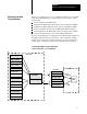
Chapter 2 Important Information That You Need to Set Up the SPI Network Example Diagram with Primary and Secondary Machine Connections In the following example, a machine has a junction box (primary machine connections) to which you may connect up to four devices (secondary machine connections). Use jumper plugs in the absence of connected devices.
Chapter 2 Important Information That You Need to Set Up the SPI Network Notes 2-8
Chapter 3 Defining Command and Status Blocks Chapter Objectives You communicate with devices on the SPI network by transferring data blocks between a PLC processor and an SPI module. In this chapter, we present the structure of data blocks and show relationships between them.
Chapter 3 Defining Command and Status Blocks Module Configuration Command Block (MCC) Your ladder logic must send (BTW) a valid MCC to the SPI module after power-up to prepare it for operation. This can be an MCC header (4 words) or a complete MCC block (up to 64 words).
Chapter 3 Defining Command and Status Blocks Table 3.
Chapter 3 Defining Command and Status Blocks System Status Block (SYS) The system status (SYS) block is returned by the SPI module on power-up with the power up bit reset (to zero) to indicate that the module is ready for a valid MCC. Until the SPI module is configured by a valid MCC, the module returns the SYS with each BTR request regardless of the device type or station address specified in the BTR request.
Chapter 3 Defining Command and Status Blocks Table 3.D Word/Bit Definitions of the System Status Block (SYS) Word Number 1 2 3 4 5 thru 18 Bit Number Title 0-7 Block ID 8 Range / Description 11111111 SYS block ID Mirrors the MCC when the entry is valid. Data Format DF 0 = decimal data Mirrors the MCC when the entry is valid. 9-10 Numeric Format NF 00 = floating point 01 = decimal data Mirrors the MCC when the entry is valid.
Chapter 3 Defining Command and Status Blocks Custom Configuration Block (CCB) The custom configuration block (CCB) tells the SPI module the required configuration for a single device, specified by the device ID in its header. Your program must transfer a CCB to the SPI module for each custom device on the SPI network. Then, your program must use custom data blocks (CDBs) to transfer data to the devices.
Chapter 3 Defining Command and Status Blocks Table 3.F Word/Bit Definitions of the Custom Configuration Block (CCB) Word Number Bit Number Title 0-7 Device ID 8-10 Determine Configuration DC (ID specific) 11 Clear All CA 12-15 Not used 0-7 1 Note 1 Note 1 Note 1 100 = Store configuration 101 = Read configuration 110 = Overwrite configuration 111 = Clear configuration Use the SPI specified device ID. > > > > If device ID matches a stored ID, SPI returns an error.
Chapter 3 Defining Command and Status Blocks Custom Data Block (CDB) Custom data blocks (CDBs) are used with custom configuration blocks (CCBs) blocks to communicate with devices on the SPI network via the SPI module.
Chapter 3 Defining Command and Status Blocks Table 3.H Word/Bit Definitions for the Custom Data Block (CDB) Word Number 1 Title Range Description SPI Device ID starts at 00100000 20 Must use the SPI specified device ID. 000= Standard Determine 001 = Custom Configuration 010 = Random Data DC 011 = Random Data Open Use 001 for custom configuration stored in SPI RAM. Not used 2 Device Address 32 to 255 decimal data Use the address that you selected on the device with switches.
Chapter 3 Defining Command and Status Blocks Custom Configuration Status (CCS) The SPI module responds to the custom configuration block (CCB) by reflecting it back to the PLC processor as custom configuration status (CCS) unless the SPI module detects: an error in the CCB it cannot store the CCB Upon detecting either of the above, the SPI module inserts error information in the CCB and returns it as the CCS as follows: sets the configuration error CE bit to 1 loads fault diagnostics into word 3 Table 3
Chapter 3 Defining Command and Status Blocks Table 3.J Bit/Word Definitions of Custom Configuration Status (CCS) Word Number Bit Number Title 0-7 Device ID 8-10 Determine Configuration DC (ID specific) 11 Clear All CA 12 Command Executed CE 13-15 Not used 1 Range SPI Module: 00100000 to 11111110 100 = Store configuration 101 = Read configuration 110 = Overwrite configuration 111 = Clear configuration mirrors the SPI specified device ID.
Chapter 3 Defining Command and Status Blocks Custom Data Status (CDS) The SPI module returns custom data status (CDS) from a custom-configured device whenever the SPI module: reads status from the device during a polling sequence acknowledges a CDB command addressed to the device The status contained in CDS is different for each of the above. If the SPI module: Then it: detects no faults 1. Sets the command executed (CE) bit 12 to 1. 2.
Chapter 3 Defining Command and Status Blocks CDS Resulting from CDB The SPI module responds to CDB commands by reflecting the CDB back to the PLC processor as the CDS (Table 3.L): Table 3.
Chapter 3 Defining Command and Status Blocks Summary of SPI Block Acronyms, Device Types, and ID Codes The following table helps you identify: acronyms of various command and status blocks that your ladder logic transfers to and from the SPI module SPI-specified ID codes of devices that you can place on the SPI network Table 3.
Chapter 4 Creating Command and Status Blocks to Match Your Application Objective This chapter helps you: map your data table for command and status blocks enter initial conditions in command blocks for transfer to the SPI module determine where you expect to find status returned from the SPI module You must do this for the following blocks: MCC and SYS CCB and CCS CDB and CDS Task Overview Map your data table for command and status blocks as follows: For Command Blocks MCC, CCB, and CDB Use command-bl
Chapter 4 Creating Command and Status Blocks Module Configuration Command Block, MCC, to Configure the SPI Module Use this worksheet for the MCC to write down: data format of all addresses and data communication rate of the SPI link number of pages of the MCC (above 1 page of 64 words) queue order in which the SPI module will poll devices on the link device ID and address code of devices in the polling queue list Example MCC Worksheet Word Write your entry in this column.
Chapter 4 Creating Command and Status Blocks Blank MCC Worksheet for Your Application Write your own entries in this blank worksheet to suit your application. MCC Worksheet Word Write your entries in this column. 1 baud rate = _______ SPI reports: Commands not Executed Y N . . .
Chapter 4 Creating Command and Status Blocks Custom Configuration Block CCB, to Configure the SPI Module for a Device You must create one CCB for each device type on the link to define: data layout of the CCB number of bit-command words and their command codes number of numeric preset words and their command codes number of ASCII string words and their command codes same information for status (independent of data sent) Important: To obtain command-code pairs CMD1 and CMD2 for specifying commands and set
Chapter 4 Creating Command and Status Blocks Blank CCB Worksheet for Your Application Write your own entries in this blank worksheet to suit your application. Important: Because we cannot predict the number of bit, numeric, or ASCII entries in your application, we give you a blank word column and extra rows for each type of entry. Enter the number of the file word for each entry, and use blank rows as needed. Enter device ID and data in the formats that you specified in MCC word 1 bits 8-10.
Chapter 4 Creating Command and Status Blocks Blank CCB Worksheet for Your Application Copy this worksheet as needed. Write your own entries in this blank worksheet to suit your application. CCB Worksheet Word Write your entries in this column.
Chapter 4 Creating Command and Status Blocks Blank CCB Worksheet for Your Application Copy this worksheet as needed. Write your own entries in this blank worksheet to suit your application. CCB Worksheet Word Write your entries in this column.
Chapter 4 Creating Command and Status Blocks Custom Data Block, CDB, to Transfer Data to the Device You must create a CDB to send data to the device. The purpose of this worksheet is to help you enter values into the words that you defined in the CCB.
Chapter 4 Creating Command and Status Blocks Blank CDB for Your Application Write your own entries in this blank worksheet to suit your application. Important: Because we cannot predict the number of bit, numeric, or ASCII entries in your application, we give you a blank word column and extra rows for each type of entry. Enter the number(s) of the file word(s) for each entry, and use blank rows as needed. Enter data, ID, and addresses in the formats that you specified in MCC word 1, bits 8-10.
Chapter 4 Creating Command and Status Blocks Blank CDB for Your Application Copy this worksheet as needed. Write your own entries in this blank worksheet to suit your application. Important: Because we cannot predict the number of bit, numeric, or ASCII entries in your application, we give you a blank word column and extra rows for each type of entry. Enter the number(s) of the file word(s) for each entry, and use blank rows as needed.
Chapter 4 Creating Command and Status Blocks Blank CDB for Your Application Copy this worksheet as needed. Write your own entries in this blank worksheet to suit your application. Important: Because we cannot predict the number of bit, numeric, or ASCII entries in your application, we give you a blank word column and extra rows for each type of entry. Enter the number(s) of the file word(s) for each entry, and use blank rows as needed.
Chapter 4 Creating Command and Status Blocks System Status Block, SYS Use this SYS bit/word map to identify: data layout of the SYS location of the diagnostic word to describe detected MCC errors location of invalid device ID and/or device address number of bits in word 5 to indicate “device OK” on link (in last row) We identify fault diagnostic information in bold print.
Chapter 4 Creating Command and Status Blocks Custom Configuration Status, CCS, to Return Configuration Status From the SPI Module Once you have successfully configured the SPI module with the MCC and whenever you transfer the CCB to the SPI module, it responds by returning Custom Configuration Status (CCS). You must correct any detected errors as indicated by the CCS before you can transfer data to devices whose configuration has been successfully stored in the SPI module.
Chapter 4 Creating Command and Status Blocks Custom Data Status, CDS, to Return Device Status From the SPI Module The SPI module receives status from the target device and returns Custom Data Status (CDS) to the PLC processor whenever the target device: receives the Custom Data Block (CDB) from the SPI module is polled by the SPI module The contents of the CDS are different for each condition: For this origin: CDS contains CDB command the reflected command code pairs that you entered in CCB polling
Chapter 5 Interpreting Diagnostic Information from LEDs and Error Codes Chapter Objectives This chapter helps you troubleshoot the SPI module using: diagnostic indicators on the front of the module diagnostic codes returned by the SPI module Troubleshooting with Diagnostic Indicators Diagnostic indicators (Figure 5.1) and (Table 5.A) indicate the SPI module’s operating status. Use them to troubleshoot your module. Figure 5.
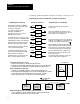
Chapter 5 Interpreting Diagnostic Information In LEDs and Error Codes Use this Flow Chart to Troubleshoot Your SPI Network Locate the SPI module in the I/O chassis and observe its LED indicators. Use the following flow charts to troubleshoot the cause of the fault: Are process actuals being read from the device, and are setpoints accepted by the device? Yes SPI communication is OK. No Observe the SPI module's LEDs.
Chapter 5 Interpreting Diagnostic Information In LEDs and Error Codes A SPI module is not configured if: MODULE ACTIVE = Flashing Is SPI module in the correct I/O slot? No Move SPI module to the correct I/O slot. No Enter or correct the device ID in the MCC polling list. Yes Is the device ID listed correctly in the polling list? Yes Is the device enabled in the polling list? No Set the DS bit 15 for the device in the MCC polling list.
Chapter 5 Interpreting Diagnostic Information In LEDs and Error Codes B SPI module is configured if: MODULE ACTIVE = ON Look at different LED. Is: MODULE FAULT No = Flashing If MF is OFF and CA is ON or flashing, communication to devices is OK. If data returned from a device is zero, check device configuration in CCB. Yes SPI module is not receiving from a device. Look up 8000 series error codes in CDS word 3.
Chapter 5 Interpreting Diagnostic Information In LEDs and Error Codes Using Diagnostic Error Codes When the SPI module detects an error, it indicates the source of the error in word 3 returned in the SYS, CCS, or CDS status block. Error codes are 4–digit hexadecimal values 0001-FFFF, grouped as follows: Error Code: Source: Returned in: Description: Refer to: 9000 series MCC SYS MCC Data Entry Errors Table 5.B 5000 series CCB CCS CCS Data Entry Errors Table 5.
Chapter 5 Interpreting Diagnostic Information In LEDs and Error Codes 9000 Series Error Codes for the MCC (Returned in SYS) When you attempt to download the MCC to the SPI module, it returns SYS with an error code each time it detects a data entry error. We list 9000 series error codes (Table 5.B) and the corresponding MCC bit/word map to show the data fields where your entered data was detected as invalid. Locate the circled number in the MCC bit/word map corresponding to the 9000 series error code.
Chapter 5 Interpreting Diagnostic Information In LEDs and Error Codes 5000 Series Error Codes for the CCB (Returned in CCS) When you attempt to download each CCB to the SPI module to configure the module for each device on the SPI network, the module returns CCS with an error code each time it detects a data entry error. We list 5000 series error codes (Table 5.C) and the corresponding CCB bit/word map to show the data fields where your entered data was detected as invalid.
Chapter 5 Interpreting Diagnostic Information In LEDs and Error Codes Error Codes Returned in CDS Error codes returned in CDS deal with communication with devices on the SPI network, and fall into two categories: commands not supported or not executed by the device (return of 7000 series codes) communication network error (return of 8000 series codes) 7000 Series Error Codes for Commands Not Supported or Not Executed A device on the SPI link can detect either of these conditions and indicate them to the S
Chapter 5 Interpreting Diagnostic Information In LEDs and Error Codes 8000 Series Communication-network Error Codes The SPI module returns these protocol-related error codes (Table 5.E) in the CDS when it detects network-related errors. Table 5.
Chapter 5 Interpreting Diagnostic Information In LEDs and Error Codes Notes 5-10
Customer Support If you need additional assistance on using your software, Allen-Bradley offers telephone and on-site product support at Customer Support Centers worldwide. For technical assistance on the telephone, first contact your local sales office, distributor, or system integrator. If additional assistance is needed, then contact your local Customer Support Center or contact System Support Services.
Allen Bradley, a Rockwell Automation Business, has been helping its customers improve productivity and quality for more than 90 years. We design, manufacture and support a broad range of automation products worldwide. They include logic processors, power and motion control devices, operator interfaces, sensors and a variety of software. Rockwell is one of the world's leading technology companies. Worldwide representation.