PLC 3 Family I/O Scanner Communication Adapter Module User Manual
Important User Information Because of the variety of uses for this product and because of the differences between solid state products and electromechanical products, those responsible for applying and using this product must satisfy themselves as to the acceptability of each application and use of this product. For more information, refer to publication SGI-1.1 (Safety Guidelines For The Application, Installation and Maintenance of Solid State Control).
Summary of Changes Summary of Changes Additional Information In general, we improved the format and added greater detail to this manual. We have also corrected incorrect and confusing concepts throughout the manual. The following table lists specific changes we made since: We have: Added details concerning 230.
Table of Contents Summary of Changes . . . . . . . . . . . . . . . . . . . . . . . . . . . . 1 1 Additional Information . . . . . . . . . . . . . . . . . . . . . . . . . . . . . . . . . 1 1 Using this Manual . . . . . . . . . . . . . . . . . . . . . . . . . . . . . . . P 1 Manual Objectives . . . . . . . . . . . . . . . . . . . . . . . . . . . . . . . . . . . What this Manual Contains . . . . . . . . . . . . . . . . . . . . . . . . . . . . . Audience . . . . . . . . . . . . . . . . . . . . . . . . .
ii Table of Contents Addressing DH and DH+ Data Transfers . . . . . . . . . . . . . . 5 1 Chapter Objectives . . . . . . . . . . . . . . . . . . . . . . . . . . . . . . . . . . . Addressing Field Parameters . . . . . . . . . . . . . . . . . . . . . . . . . . . Interpreting Addresses . . . . . . . . . . . . . . . . . . . . . . . . . . . . . . . . Addressing Data . . . . . . . . . . . . . . . . . . . . . . . . . . . . . . . . . . . . Specifying Addresses . . . . . . . . . . . . . . . . . . . . . . . . . .
Table of Contents iii DH/DH+ Diagnostic Assignment Command . . . . . . . . . . . . . . . . . 7 11 Binary Command Language . . . . . . . . . . . . . . . . . . . . . . . A 1 Introduction . . . . . . . . . . . . . . . . . . . . . . . . . . . . . . . . . . . . . . . . Protocol . . . . . . . . . . . . . . . . . . . . . . . . . . . . . . . . . . . . . . . . . . Extended Addressing . . . . . . . . . . . . . . . . . . . . . . . . . . . . . . . . . Commands . . . . . . . . . . . . . . . . . . . . . . . . . . .
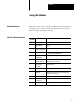
Preface Using this Manual Manual Objectives What this Manual Contains This preface tells you how to use this manual properly and efficiently for the tasks you have to perform. Read this chapter before you program a PLC-3 family programmable controller.
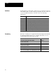
Preface Audience In this manual, we assume that you know how to program and operate an Allen-Bradley PLC-3 or PLC-3/10 programmable controller system. If you are not familiar with these controllers, refer to the following publications: Publication Vocabulary P- 2 Title 1770 6.2.2 Data Highway Cable and Data Highway Plus Installation Manual 1770 6.5.15 PLC 3 Industrial Terminal (cat. no. 1770 T4) User's Manual 1770 6.5.16 Data Highway/Data Highway Plus Protocol Command Set User's Manual 1771 6.
Preface In addition, you may encounter words in different typefaces. We use these conventions to help differentiate descriptive information from information that you enter while programming your scanner. The Return key looks like this (boldface and in brackets): [Return] Words or commands that you enter appear in boldface. For example: $047 $FILE_A Variables that you enter appear in italics.
Chapter 1 Scanner Hardware and Installation Chapter Objectives This chapter describes: the features and functions of the 1775-S5, -SR5 scanners the hardware components on the scanner how to install the scanner how to connect and configure the scanner to a(n): - backup system - Data Highway (DH) or Data Highway Plus (DH+) communication network - I/O adapter for I/O scanning - programming terminal - scanner in another PLC-3 or PLC-3/10 chassis Scanner Features and Functions The 1775-S5, -SR5 scanner has
Chapter 1 Scanner Hardware and Installation Table 1.A 1775 S5, SR5 Scanner Features and Functions Features 1-2 Functions Four I/O communication channels Communicate with I/O adapter modules in an I/O chassis. You can connect up to 32 I/O chassis to one I/O channel. The scanner can communicate with up to 4,096 I/O. I/O scan priority Scan the I/O chassis according to a sequence that you select. DH/DH+ channel Communicate with other Allen Bradley controllers and/or computers on a DH or a DH+ channel.
Chapter 1 Scanner Hardware and Installation Hardware Features Figure 1.1 shows the hardware components on your scanner. Figure 1.1 Hardware Features on the Scanner 1775 S5 Scanner 1775 SR5 Scanner PASS and FAIL indicators Thumbwheel switch Forces enabled indicator I/O channel status indicators DH/DH+ status indicators Backup connector DH/DH+ connectors I/O channel terminal arm The scanner also has switch settings located on the top and bottom edges.
Chapter 1 Scanner Hardware and Installation Pass and Fail Indicators The indicators labeled PASS and FAIL (Figure 1.2) keep you informed about the general condition of the scanner: PASS (green) FAIL (red) Meaning on off normal operation off on module fault on on power up or system reset off off system is not on or module has lost power Forces Enabled Indicator The yellow indicator labeled FORCE (Figure 1.2) illuminates when I/O forcing is enabled in the system.
Chapter 1 Scanner Hardware and Installation DH/DH+ Status Indicators The five indicators labeled XMTG, RCVG, RDY, ERR, and DIS (Figure 1.2) show you the status of the DH or DH+ channel. Indicator Color When this led is on, (the scanner is) XMTG green transmitting a message. RCVG green receiving a message. RDY green ready to transmit a message. ERR red DIS yellow programming or communication error detected. DH/DH+ connectors are disabled or duplicate DH+ station address if blinking.
Chapter 1 Scanner Hardware and Installation Configuring the Scanner Hardware Before you install the scanner, you need to configure the module. You use the connectors, terminal arm, and switches when: setting the thumbwheel and switches installing the scanner We describe these connections and configurations in the following sections. Setting the Thumbwheel and Switches Before inserting the scanner into a chassis: 1.
Chapter 1 Scanner Hardware and Installation When a channel is configured for a communication rate of 230.4 kbps, the corresponding terminator switch must be up away from the board. An external 82 ohm terminator must be used in this configuration. Figure 1.4 Setting a Terminator on a Communication Channel Up (away from board) 1 2 3 Down (toward board) 4 When DOWN, a 150 ohm terminator is connected on the corresponding communication channel.
Chapter 1 Scanner Hardware and Installation Not all DH+ stations are capable of operating above 57.6 kbps. You must reference the appropriate users manual for the maximum communication rate for each device. ATTENTION: Channel 4 may not be configured for DH or DH+ when operating any of the other communication channels at 230.4 kbps. Otherwise, I/O rack retries and missing inputs in a listen only mode backup system may result. Figure 1.
Chapter 1 Scanner Hardware and Installation Figure 1.6 Setting the Station Number for the DH or DH+ Channel If you are using channel 4 for DH or DH+ communication, then set the station number with these switches.
Chapter 1 Scanner Hardware and Installation Setting Backup System Functions On the bottom edge (Figure 1.7) near the rear of the scanner is a set of 4 switches. If you are using a backup configuration, then you can set switches 2 and 3 to define the switchover type. For detailed information on backup, refer to the PLC-3 Backup Concepts Manual (publication 1775-6.3.1). Figure 1.
Chapter 1 Scanner Hardware and Installation The chassis electromechanically interlocks helping to guard against inserting or removing modules while power is on. ATTENTION: Do not change the thumbwheel setting on a scanner while power is on. This could result in equipment damage. PLC-3 and PLC-3/10 systems require a scanner with the thumbwheel set to 1. If you are using a multi-chassis system, the scanner set to 1 must be in the chassis with the front panel.
Chapter 1 Scanner Hardware and Installation Connecting to a Backup System With a backup system, if a major fault occurs, the primary system shuts down and the backup system takes over the outputs to enable your process to continue. To set up a backup system, connect a backup cable (cat. no. 1775-CBA, -CBB) from the 6-pin connector labeled BACK UP on scanner number 1 in a primary system to the backup connector on scanner number 1 in a backup system (see Figure 1.8). Figure 1.
Chapter 1 Scanner Hardware and Installation Connecting to a DH or DH+ Network The scanner enables the connectors labeled DH/DH+ when you set communication channel 4 for a DH or DH+ link. You can use the: 9-pin connector to connect the programming terminal for programming the processor on a DH+ network 3-pin connector to connect the controller to a DH or DH+ netwrok Programming Terminal Connections The 9-pin connector provides direct connection via the Industrial Terminal Processor Cable.
Chapter 1 Scanner Hardware and Installation Figure 1.
Chapter 1 Scanner Hardware and Installation To make connections to the scanner, connect the 1770-CD cable to the screw terminals on the 3-pin connector (Figure 1.10). Figure 1.10 Connecting the Scanner to a DH or DH+ Terminals on the scanner Connecting the scanner to another scanner on a DH or DH+ link 1 Clear Clear 1 SH Shield Shield Blue Blue SH 2 2 Clear 8 SH Shield Shield Blue Blue Connecting the scanner to a computer via a Series B 1770 KF2 module on a DH or DH+ link.
Chapter 1 Scanner Hardware and Installation Connecting to the I/O Channel Terminal Arm The terminal arm provides connections for four I/O communication channels (Figure 1.11). Functions of these channels include: I/O communication backup communication peer-to-peer communication If you select: Then the maximum I/O channel cable length can be: 57.6 kbps 10,000 feet 115.2 kbps 5,000 feet 230.
Chapter 1 Scanner Hardware and Installation Electrostatic Discharge ATTENTION: Electrostatic discharge can degrade performance or damage the module. Electrostatic discharge can damage integrated circuits or semiconductors in the scanner if you touch backplane connector pins. It can also damage the scanner when you set configuration plugs and/or switches inside the module.
Chapter 2 Configuring the Scanner through LIST Chapter Objectives You use LIST function to configure the scanner. This chapter describes the LIST selections.
Chapter 2 Configuring the Scanner through LIST The heading for this menu shows the scanner’s thumbwheel setting and slot location in the processor chassis. Selections 6 and 7 only display for scanner number 1. We describe these selections in the rest of this chapter. Figure 2.
Chapter 2 Configuring the Scanner through LIST Configuring the Communication Channels To configure channels 1 through 4, you select the following parameters: communication rate (bps) (page 2-3) operating mode (page 2-4) auto configuration (page 2-4) reconfiguration (page 2-5) I/O scan configuration (page 2-6) peer-to-peer master configuration (page 2-8) peer-to-peer slave configuration (page 2-8) backup communication configuration (page 2-9) DH or DH+ configuration (channel 4 only) (page 2-10) Communicat
Chapter 2 Configuring the Scanner through LIST Operating Mode You can select one of the following operating modes for the corresponding communication channel: inactive I/O scan peer-to-peer master peer-to-peer slave backup communications DH communications (channel 4 only) DH+ communications (channel 4 only) These selections identify what the channel is being used for. The default is I/O scan. An asterisk (*) displays next to the current mode of the channel.
Chapter 2 Configuring the Scanner through LIST You can only perform an auto configuration when: the controller is in program load mode power is applied to the I/O chassis the processor restart lockout switch is set to allow the I/O chassis to be restarted from the processor If power is not applied to the I/O chassis, the processor attempts to perform an auto configure, and since the I/O chassis does not respond, the scanner does not enter it in the I/O chassis list.
Chapter 2 Configuring the Scanner through LIST ATTENTION: Selecting reconfiguration while the controller is in the run mode and executing block transfers could cause a bad address fault. If this situation occurs, you should: Clear the bad address fault in a fault routine. Clear the block transfer error bit. Restart the block transfer in the ladder program I/O Scan Configuration When you configure an I/O channel for I/O scan, you can change the order and priority that the scanner scans the I/O chassis.
Chapter 2 Configuring the Scanner through LIST To delete entries from the list, press: entry/d [Return] When forming this list, remember: Selection of I/O rack numbers greater than 378 increases the program scan time. I/O rack numbers that are not assigned consecutively cause greater memory requirements because memory has to be allocated for the unused racks. You can connect up to 32 I/O adapters to one I/O communication channel on a scanner.
Chapter 2 Configuring the Scanner through LIST Peer to Peer Master Configuration When you configure a channel as a master on a peer-to-peer communication channel, you must enter the following parameters: Parameter Description Master number identifies the master for communication with the slaves. Each peer to peer communication channel can have one master only. The master number and all slave numbers must be unique and selected from numbers 81 through 89.
Chapter 2 Configuring the Scanner through LIST LIST displays the size of the input and output files. For example, I1:0 → 19 shows that input file 1 contains 20 octal words. You can create a larger file by entering the last word desired in the file when prompted for the file number in LIST. By entering I1:50 for the input file, the system will automatically increase input file 1 to 50 octal words.
Chapter 2 Configuring the Scanner through LIST DH or DH+ Configuration When you configure channel 4 for DH or DH+ communication protocol, you can set the following parameters: node mode (page 2-11) station number (page 2-11) DH/DH+ timeouts (page 2-12) backup operation (page 2-13) send unprotected (page 2-14) accept upload/download (page 2-15) accept writes (page 2-15) input file list (page 2-16) privileges (page 2-17) DH/DH+ switch settings (page 2-18) DH+ active node list (page 2-19) DH+ active nodes to
Chapter 2 Configuring the Scanner through LIST 1 - Node Mode Select the NODE MODE option from the configuration screen to allow or disallow the station communicating on the link. By selecting NODE MODE, you can configure the channel to be online or offline. If you select: Then the channel is: on line an active station on the link. off line inactive and the DH/DH+ disable indicator is turned on. Important: A reconfigure is not necessary to change this selection.
Chapter 2 Configuring the Scanner through LIST 3 - DH/DH+ Timeouts Select the DH/DH+ Timeouts option to set these timeout values in seconds: outgoing message LIST channel remote program Outgoing Message This timeout is the maximum amount of time that the scanner waits for another station to reply to one of the messages. The valid entries are 0 to 999.9. In LIST, you can enter timeout values as whole numbers or in tenths of seconds.
Chapter 2 Configuring the Scanner through LIST 4 - Backup Operation Select the Backup Operation option from the configuration screen to configure the DH and DH+ station numbers when backed up. See Table 2.A. Table 2.A Backup Operation Options If backup is: The DH and DH+ station number of the backup scanner module: Selected is automatically modified before and after switchover. This allows you to have identical configurations in both the primary and the backup processor.
Chapter 2 Configuring the Scanner through LIST Table 2.C DH+ Station Numbers for 1775 S5, SR5 Modules If the station address between: The backup scanner module assumes a station address that is: 00 and 378 408 higher than the assigned station number 408 and 778 408 lower than the assigned station number When you do not select backup, you assign a unique DH (0008 to 3768) or DH+ (008 to 778) station number to the scanner module in the primary processor and the one in the backup processor.
Chapter 2 Configuring the Scanner through LIST 6 - Accept Upload/Download Select the Accept Upload/Download option from the configuration screen to determine if the scanner can execute upload and download commands sent by another station. You use a sequence of upload and download commands to transfer memory information from the controller to another station or from another station to the controller.
Chapter 2 Configuring the Scanner through LIST 8 - Input File List (PLC 2 Compatibility Mode Only) Select the Input File List option from the configuration screen for a list of files that the scanner accesses when receiving data using PLC-2 logical data addressing (see chapter 5). When a PLC-2 command comes in from a station on a DH or DH+ link, the scanner accesses the input file associated with that remote station number. You must make sure the input file is created in memory.
Chapter 2 Configuring the Scanner through LIST To add a station address and input file to the list, enter a colon (:) followed by the station address, a space, and the input file number. For example: INPUT FILE LIST STATION FILE :0 2 :5 2 :64 6 :65 7 1:37 4 ENTER STATION AND INPUT FILE #> :6 4 You can specify an octal station number by starting it with a leading 0. Otherwise, the scanner treats it as a decimal number. The file number is always treated as a decimal number.
Chapter 2 Configuring the Scanner through LIST Available privileges are: Privilege Number 0 1 2 3 4 5 6 7 8 10 64 65 66 67 68 69 70 71 72 73 74 Allows the device on the channel to write to the system status area of memory write to the system pointers area of memory write to the module status area of memory write to the data table area of memory write to the ladder program area of memory write to the message area of memory write to the system symbols area of memory write to the system scratchpad area of me
Chapter 2 Configuring the Scanner through LIST When you select this option, the programming terminal displays: DH/DH+ SET-UP SWITCH SETTINGS (VIEW FROM TOP OF MODULE) S1 DOWN/ON X X UP/OFF SWITCH # 8 7 S2 X X X 6 5 4 X X 3 X X 2 1 1 EXIT THIS MENU ENTER NEXT > 4 63 NOTE: X 2 1 X STATION NUMBER IN OCTAL CURRENT SELECTION X MODULE FRONT 3 MODE BAUD DH+ 57.
Chapter 2 Configuring the Scanner through LIST 12 - DH+ Active Nodes to Status File 6 Select the DH+ Active Nodes to Status File 6 option from the configuration screen to maintain the DH+ active node table in status file 6. The list of active nodes is stored in status file 6. If you enable this option, you must also create status file 6. Status file 6 is partitioned into 4 words for each of the 15 possible scanner thumbwheels. To provide for 15 scanners, you must create S6:59.
Chapter 2 Configuring the Scanner through LIST I.T. Defaults / Configuration The I.T. defaults selection in LIST configures channel 0 for Binary Command Language (BCL) protocol communication with an industrial terminal (see appendix A). You can use the industrial terminal as a programming terminal for such functions as ladder programming. When you select I.T. defaults, the default values are used as shown in the following table.
Chapter 2 Configuring the Scanner through LIST Reconfiguration This selection implements changes that you have made in LIST for channel 0. If channel 0 is being used when you reconfigure it, the changes are not implemented until communication on the channel is terminated and then re-established. An asterisk appears next to Reconfigure when a change has been made to any of the channel 0 parameters. The asterisk is removed after a successful reconfigure.
Chapter 3 I/O Communication Chapter Objectives This chapter describes timing and programming considerations when using the scanner for I/O communication and helps you learn how: I/O scan affects ladder program execution to calculate block-transfer times to program and calculate times for a peer-to-peer or backup communication channel Effect of I/O Scan on Program Execution You must remember that in scanning the ladder program and the I/O: input changes do not instantly appear in the input image table.
Chapter 3 I/O Communication Table 3.A I/O Scan per I/O Chassis in Milliseconds Number of Active I/O Channels bps Chan 4 Config 1 2 3 4 57.6k Not DH/DH+ DH/DH+ 7 8 7 8 7.5 9 8 N/A 115.2k Not DH/DH+ DH/DH+ 4.5 5 5 6 5 7 6.5 N/A 230.4k Not DH/DH+ DH/DH+ 3 N/A 3.5 N/A 5 N/A 6 N/A Each I/O chassis that you add to the scanning sequence list (including repeated I/O chassis in the list) increases the I/O scan time.
Chapter 3 I/O Communication Table 3.B Nominal Block Transfer Times in Milliseconds for a Block transfer Instruction Channels with block transfer I/O modules Number of active channels 1 2 3 4 1 27 27 28 35 2 x 29 30 36 3 x x 31 38 4 x x x 40 4. Count the number of block-transfer I/O modules on the channel. If the chassis containing a block-transfer I/O module appears more than once in the I/O chassis scanning list, count the module once each time the chassis appears in the list.
Chapter 3 I/O Communication Figure 3.1 Using a Peer to Peer Communication Channel Slave A Master Slave B Twinaxial cable for setting up peer to peer communication channel. 15410 You configure the master and slave controllers for the peer-to-peer channel through LIST. Communication occurs via files that you specify in LIST. Figure 3.2 shows the communication flow between master and slave controllers on a peer-to-peer channel. Figure 3.
Chapter 3 I/O Communication Programming Peer to Peer Communication Programming PLC-3 family controllers for peer-to-peer communication requires that the ladder program in the: master transfers the appropriate data to its output file receiving slave knows the proper use for each word in its input file The controller automatically handles the actual data transfer. Each slave’s input file must be equal to or larger than the master’s output file. Otherwise, a peer-to-peer communication minor fault occurs.
Chapter 3 I/O Communication Important: You can control the information that is transferred by using multiple rungs to transfer different information to the output file, depending on the rung conditions. However, remember that the output file contains only the last data that moves into each location. The peer-to-peer transfer is independent of program scan and a file can be transferred before being fully updated by the ladder program. Figure 3.
Chapter 3 I/O Communication Important: Remember to reset the counter for the MVF, or the move operation does not function properly. Backup Communication You can use the backup communication with the PLC-3 or PLC-3/10 backup feature. The backup feature has an I/O listening mode that enables the backup system to monitor input data. To transfer other information to the backup system, you can install a backup communication channel (Figure 3.5).
Chapter 3 I/O Communication Figure 3.6 Communication Flow Between Primary and Backup Controllers on a Backup Communication Channel Primary System Processor Memory Backup System Processor Memory output file input file input file output file Each input file must be large enough to store the data from the corresponding output file. Otherwise, a backup communication minor fault occurs.
Chapter 3 I/O Communication Figure 3.7 shows example rungs using the run/backup bit (S000:3/17). To use these rungs for backup communication, you must enter them into the primary and backup systems. The run/backup bit is set in the primary system and reset in the backup system. The counter is updated only in the backup system. In this example, both the primary and backup systems use input file 1 as the input file and output file 1 as the output file for the backup communication channel.
Chapter 3 I/O Communication Calculating Peer to Peer and Backup Communication Times The time required to transfer a file across a peer-to-peer or backup communication link depends on the number of: active channels on the scanner communication rate words in the output files To calculate the time needed to update every input file on the link, use the following procedure: 1. Determine the number of words in all output files of the master and each slave on the peer-to-peer communication link.
Chapter 3 I/O Communication To calculate the time needed to update a specific input file on the peer-to-peer or backup communication link, use the following procedure: 1. Determine the number of words in the output file being sent to this specific input file. Divide by 8 and round up. 2. Determine the total number of slaves on the link. 3. Determine the greatest number of active channels on any scanner on the peer-to-peer communication link. 4. Find the nominal peer-to-peer time by using Table 3.
Chapter 3 I/O Communication Figure 3.8 Example Configuration for a Peer to Peer Communication Channel Peer to Peer Communication Channel A Processor A (Master) Peer to Peer Communication Channel A Processor B (Slave) Processor C (Slave) Peer to Peer Communication Channel I/O Channel Peer to Peer Communication Channel I/O Channels Peer to Peer Communication Channels Note: All Peer to Peer and I/O Channels connect to the Terminal Swing Arm of the Scanner Module as shown in Figure 1.11.
Chapter 4 DH and DH+ Communication Chapter Objectives This chapter introduces some of the concepts and terminology involved with operating the scanner on a DH or DH+ communication. Introduction The Allen-Bradley DH and DH+ links are communication networks for industrial control applications. Both links consist of a central trunkline cable that can be up to 10,000 feet long. This cable can link together as many as 64 distinct communication points (or nodes) called stations (Figure 4.1).
Chapter 4 DH and DH+ Communication Table 4.
Chapter 4 DH and DH+ Communication Figure 4.
Chapter 4 DH and DH+ Communication Communication Terms Stations communicate with each other by sending two types of messages over a link: Type of messages: Function: command messages either gives (writes) data to, or requests (reads) data from one station to another. reply messages is a station's response to a command message. You program command messages into the scanner. Execution of a message command is controlled by the message (MSG) instruction in the ladder program.
Chapter 4 DH and DH+ Communication In read operations, the command message requests the data transfer, but the corresponding reply message actually contains the data being transferred. In write operations, the command message contains the data being transferred, and the reply message merely reports the status (receipt or non-receipt) of the transfer. Levels of Programming The PLC-3 processor must be free to control its own processes at the same time that the scanner is communicating over a DH or DH+.
Chapter 4 DH and DH+ Communication Ladder Program The first link in the communication process is your ladder program. You send a DH/DH+ command message by means of the message (MSG) instruction (Figure 4.2). When the rung becomes true, the processor informs the scanner to begin sending command(s) across the link. At the same time, bits in a control file word change their state (Table 4.B) to reflect the status of the message instruction.
Chapter 4 DH and DH+ Communication You specify the scanner that receives the command with an extended address. This address always takes the form: E2.3.nn Where: Function: E2 specifies that this command addresses the module status area of memory 3 specifies that you are sending the message instruction through the scanner nn is replaced with the thumbwheel setting on your particular scanner (1 15) To enter a message instruction, do the following: 1.
Chapter 4 DH and DH+ Communication Data Transfers The purpose of DH/DH+ communication is to transfer data from one station processor memory location to another. To accomplish these data transfers, you can program the assignment command into the scanner. Figure 4.3 is an example of an assignment command line. For details, see chapter 5. Since the following example does not specify a remote station, this transfer occurs within the local systems memory. Figure 4.
Chapter 4 DH and DH+ Communication Figure 4.4 Two Ways to Use Message Commands 1) as a single command in a PLC-3 message instruction MSG 10012 01 MESSAGE TYPE 1 CTL = FB200:0000=200 CHANNEL: E2.3.1 $B45:21=$112:33 2) as part of a message procedure Message Procedure PROC_A STAT EN 12 (other commands) STAT DN 15 STAT ER 13 $B45:21 = $112:33 (other commands) PLC-3 Message Instruction to Control Execution of Procedure PROC_A MSG 10012 01 MESSAGE TYPE 1 CTL = BW200:0000=200 CHANNEL: E2.3.
Chapter 4 DH and DH+ Communication PLC-2 Stations For communication with a PLC-2 station, write access privilege depends on switch settings at that remote station. For an explanation on how to set the switches for write access, refer to the Communication Adapter Module User’s Manual (publication 1771-6.5.1). Accessing a PLC-2 Station Access to a PLC-2 station also depends on the type of command transmitted to that station.
Chapter 4 DH and DH+ Communication Accessing a PLC-3 Processor from a PLC-2 Processor While a PLC-3 controller can address any area of a PLC-2 data table, a PLC-2 reads an input file that is a part of the PLC-3 data table. That file is the PLC-3 input file with a number that corresponds to the station number of the PLC-2 station.
Chapter 4 DH and DH+ Communication PLC-4 Stations PLC-4 stations can only communicate on a DH. To read or write to a PLC-4 station, you can send either protected or unprotected commands. Switches: at the 1773 KA module specify whether the PLC 4 station accepts unprotected or protected commands, respectively through the: 2 and 3 (on the second row of switches) DH port of the 1773 KA module. 1 and 3 (on the third row of switches) RS 232 C port of the 1773 KA module.
Chapter 4 DH and DH+ Communication Calculating DH and DH+ Communication Times The time required for the scanner in a local station to send or receive a message with a scanner in another station on a DH or DH+ link generally depends on the number of: stations on the DH+ link messages transmitted from active stations bytes of data of all transmitted messages message requests that are queued ahead of the subject message Table 4.
Chapter 4 DH and DH+ Communication Operating Backup Configurations on a DH or DH+ Link When using a scanner for DH or DH+ communication, you can set up two types of backup configurations: two scanners in the same processor chassis for backing up the link Both scanners are active, and each one is an independent station on the link. You assign unique station numbers to each scanner. If you want to send the same message through both scanners, you must program separate message instructions.
Chapter 5 Addressing DH and DH+ Data Transfers Chapter Objectives In chapter 4, we described how you can send a single message command or a message procedure containing a group of commands. This chapter explains some general rules for specifying data addresses in message procedures for communicating over a DH or DH+ link. Addressing Field Parameters To transfer data from one DH or DH+ station to another, you program an assignment command into the scanner.
Chapter 5 Addressing DH and DH+ Data Transfers In addressing individual bits, parentheses have no effect on the address interpretation. The scanner interprets the bit address bit as an octal number if it starts with a leading zero and as a decimal number if it does not start with a zero.
Chapter 5 Addressing DH and DH+ Data Transfers The S5 and SR5 scanners offer four different addressing methods for use in DH and DH+ assignment commands: PLC-2 Logical Data Addressing PLC-3 Logical Binary Addressing Logical ASCII Data Type Addressing Logical ASCII Word Range Addressing Although the scanner can transmit and receive any of these addressing methods, not all remote stations are able to interpret these methods. Table 5.A indicates which addressing methods are accepted by other controllers.
Chapter 5 Addressing DH and DH+ Data Transfers You can only address a group of words as the source field in an assignment command. The destination must be a file that is as large as, or larger than, the source size plus the offset. Figure 5.
Chapter 5 Addressing DH and DH+ Data Transfers Using PLC 3 Logical Binary Addressing When you use a PLC-3 logical binary address, the scanner transmits the address to the remote station as a six level extended address. This addressing method is normally reserved for communication between PLC-3 scanners since the receiving station must be able to interpret this form of addressing (see Table 5.A). The following rules apply when specifying a PLC-3 logical binary address: 1.
Chapter 5 Addressing DH and DH+ Data Transfers Addressing Words To address a group of consecutive words in memory, use one of the following formats: Format: Example: wordaddr,size $N0:47,20 filesym:offset,size @FILE_A:15,25 wordsym,size @WORD_1,20 You can only address a group of words as the source field in an assignment command. The destination must be a file that is as large as, or larger than, the source range. Figure 5.
Chapter 5 Addressing DH and DH+ Data Transfers Refer to the PLC-3 Family Controller Programming Manual (publication 1775-6.4.1) for detailed information on extended addressing. Addressing a Bit To address a specific bit within a word, use one of the following formats: Format: Example: wordaddr/bit $N0:47/015 filesym:offset/bit @FILE_A:15/8 wordsym/bit @WORD_1/012 Figure 5.
Chapter 5 Addressing DH and DH+ Data Transfers Using Logical ASCII Addressing The logical ASCII addressing method allows you to communicate with another device by specifying an address based on the internal memory structure of the target device. The scanner sends the address as a string of ASCII characters to the remote station. Upon receiving the string of ASCII characters, the remote station converts the data into a usable logical address.
Chapter 5 Addressing DH and DH+ Data Transfers Logical ASCII data type addressing treats data being received and sent from the floating-point data table section as a special case. The PLC-3 stores floating-point data using DEC-F format and the PLC-5 family store the same data using IEEE format. To handle this, whenever you send floating-point data using logical ASCII data type addressing, the scanner translates the data into IEEE format before transmitting on the link.
Chapter 5 Addressing DH and DH+ Data Transfers Addressing Stations on a Local Link Figure 5.8 shows the format for addressing data at remote stations on a local link. The pound sign (#) specifies a remote station on a DH or DH+ link. Figure 5.
Chapter 5 Addressing DH and DH+ Data Transfers Addressing Stations on a Remote Link In DH+ protocol, you can use the format shown in Figure 5.9 to address a remote station that is located across a bridge on another link. If you have the scanner configured for DH protocol, using this format causes a communication error to occur. Figure 5.9 Example for Addressing a Remote Station Located on a Remote DH+ Link # H 5 : 13 : 050 .
Chapter 5 Addressing DH and DH+ Data Transfers Figure 5.10 Example Assignment Command that Addresses a Remote Station #H024 $B45:21 = $I12:33 Source Address Address Delimiter Assignment Command Destination Address Address Delimiter Remote Station Number (octal) Data Highway Port Identifier Remote Station Delimiter 11242 Assignment Command You can use the assignment command to copy data from a source location to a destination location (Table 6.D).
Chapter 5 Addressing DH and DH+ Data Transfers Formatting an Assignment Command The equal sign (=) is the assignment command. The destination is on the left of the equal sign, and the source is on the right. When the scanner executes an assignment command, it assigns or copies the source value to the destination. For example: $I12:024 = US_5 The scanner copies the value of user symbol US_5 into word 24 (octal) of input file 12 (see “Using Symbols,” page 6-4).
Chapter 5 Addressing DH and DH+ Data Transfers Important: The scanner ignores the message priority modifier for DH+ messages. Command Message Type Command messages can be protected or unprotected: Protected commands can access only specified areas of data table memory at a PLC-2 station. You need to send a protected write command only if a switch at the remote PLC-2 station prohibits other stations from sending unprotected write commands. Unprotected commands can access any area of the data table.
Chapter 5 Addressing DH and DH+ Data Transfers Programming Examples of Assignment Commands This section gives examples of assignment commands using the four available addressing methods. Often, the choice of addressing method and the structure of the data table section which is being addressed, determines what data is actually sent. Timers, counters, high-order integers, floating point, and pointers are all stored in the PLC-3 memory as multiple words.
Chapter 5 Addressing DH and DH+ Data Transfers Table 5.C PLC 3 Logical Binary Addressing Binary Addressing Description #H02$F0:0 = $F0:0,6 write 6 contiguous words beginning with floating point file 0, word 0 to remote station 2 floating point section file 0 word 0. A total of three complete floating point words (2 words each) are being transferred. $D0:0 = #H054$E0.0.0.14 read the year from the system clock of remote station 45 and store the data in decimal file 0, word 0.
Chapter 5 Addressing DH and DH+ Data Transfers Table 5.E Logical ASCII Word Range Addressing Word Range Addressing Description #H024$’D1:0’ = $D1:0,2 write two words beginning with decimal file 1, word 0 into remote station 24's decimal file 1, word 0. #H040$’@PUNCH’ = $A1:0 write the data stored at ascii file 1, word 0 into remote station 40 which will store the data at the address defined by symbolic address @PUNCH. This symbol must be created and defined in the remote station.
Chapter 6 Programming DH and DH+ Message Procedures Chapter Objectives This chapter explains how to create, edit, and use the message instruction to operate the DH and DH+ communication channel on the scanner.
Chapter 6 Programming DH and DH+ Message Procedures Editing the Message Instruction The general steps for editing a DH or DH+ message procedure are: 1. Create and edit the ladder program containing message instructions that control execution of the message procedure. 2. Allocate memory to the necessary data files. 3. Create and edit the message procedure. You can perform these steps through your programming terminal.
Chapter 6 Programming DH and DH+ Message Procedures Figure 6.1 Examples of Message Instructions Reading word 5 of binary file 3 at station 045 into word 17 of integer file 4. MSG I0012 MESSAGE TYPE CTL=FB200:0000=000 CH:E2.3.1 $N4:17=#H045$B3:5 01 Destination (local) 1 STAT EN 12 STAT DN 15 STAT ER 13 Source (remote) Execute procedure @PROC_A MSG I0012 MESSAGE TYPE CTL=FB200:0000=000 CH:E2.3.
Chapter 6 Programming DH and DH+ Message Procedures Editing Message Procedures Table 6.B shows how to edit a message procedure through an RS-232-C data terminal connected to a 1775-GA module. Table 6.B Editing a Message Procedure Through an RS 232 C Data Terminal Prompt (if any) Action Keystrokes GA1> Enter the edit mode and create the message procedure name. The GA module creates the symbol definition for the message procedure name. EDIT/H @PROC1 [RET] * Enter the insert mode for editing.
Chapter 6 Programming DH and DH+ Message Procedures You cannot use certain words and character combinations as symbols because they are reserved for special uses in message procedures. The reserved words are: CREATE DELETE ERROR EXIT GOTO IF ON_ERROR STOP PROT UNPRO You also cannot use any abbreviated form of the above words. For example, you cannot use the single letter C as a symbol because it is an abbreviation of the word CREATE. Similarly, PRO is an invalid symbol.
Chapter 6 Programming DH and DH+ Message Procedures Using User Symbols A user symbol represents a numeric value. You can generate a user symbol and assign a value to it by means of the assignment command (see chapter 5). Type Description procedural The scanner recognizes procedural user symbols only in the procedure that you generate it in. interprocedural The scanner recognizes interprocedural user symbols in the procedure that you generate it in and any other procedure nested within that procedure.
Chapter 6 Programming DH and DH+ Message Procedures Using Expressions Expressions use operators to combine two or more numeric values into a single value. Table 6.C lists the operators that you can use in an expression. We list these operators from highest priority (1) to lowest priority (10). The result of an expression depends on the order the scanner executes the operations. The order of execution depends on the type of operator and on left-to-right placement within the expression.
Chapter 6 Programming DH and DH+ Message Procedures For example, the following command stores the value 12 in word 45 of binary file 67. $B67:45 = 6+3*2 This occurs because the scanner multiplies before it adds. If an expression contains several operators within the same order of execution, the scanner executes those operators in the left-to-right order in which they appear within the expression. You can enter extra sets of parentheses to change the order of execution.
Chapter 6 Programming DH and DH+ Message Procedures Bit Operator The bit operator allows you to address a specific bit of a value stored under a user symbol. For example: $l12:24/7 = US_13/4 This statement puts the value (0 or 1) of bit number 4 of user symbol US_13 into input file 12, word 24, bit 7. The bit address itself can also be a user symbol or an expression. For example: $l12:24/7 = US_3/(4+US_1) The expression (4+US_1) specifies a particular bit within user symbol US_3.
Chapter 6 Programming DH and DH+ Message Procedures Bitwise Operators Bitwise operators manipulate the individual bits in a 32-bit operand. The bitwise 32-bit complement (.BNOT.) inverts the state of each bit in the 32-bit expression. That is, bits set to 1 invert to 0, and bits set to 0 are invert to 1. The bitwise 32-bit AND (.BAND.) forms a bit-by-bit logical AND of two 32-bit operands. No carry occurs from one bit position to the next within the operand.
Chapter 6 Programming DH and DH+ Message Procedures Shift Operators The scanner supports the following shift operators: If you see: It means the bit shifts: << left >> right The shift operators shift binary values a specified number of bit positions to the left or right. When a left arithmetic shift (<<) executes, zeros shift into the rightmost bits of the expression. The leftmost bits shift out of the expression and are lost, thus possibly changing the sign bit.
Chapter 6 Programming DH and DH+ Message Procedures Since the leftmost bit of an expression is the sign bit, this means that the right bit shift on a 32-bit value does not change the sign of the numeric value. The rightmost bits still shift out of the value and are lost as shown in the following examples: GRINDER = (GRINDER >> 1) GRINDER Value: Bit Pattern (32 bits): Decimal Value: Before operation 100...00000101 -2147483643 After operation 110...
Chapter 6 Programming DH and DH+ Message Procedures Message Procedure Commands The scanner has its own command language that you can use in programming message procedures. Table 6.D summarizes these commands. Table 6.D Message Procedure Commands Command Format and Explanation (assignment) destination = source See page: Assign a numeric value to a user symbol or copy data from the source to the destination (see chapter 5).
Chapter 6 Programming DH and DH+ Message Procedures CREATE Command The CREATE command generates a symbolic address and assigns it to a logical address. To create a local symbolic address, use the CREATE command by itself (the default modifier /LOCAL is optional). To create a global symbolic address, use the modifier /GLOBAL after the CREATE command.
Chapter 6 Programming DH and DH+ Message Procedures Execute Command To execute a message procedure, enter the delimiter @ followed by the procedure’s name. For example: @FIRST_PROC The scanner executes the procedure FIRST_PROC. You can use procedure names anywhere that commands are used. This way one procedure can execute (call) another procedure. This allows for nesting of procedures. However, you cannot nest more than 3 layers deep.
Chapter 6 Programming DH and DH+ Message Procedures IF Command The IF command makes logical decisions in the message procedure. The first parameter of the IF command is an expression (see “Using Expressions,” page 6-7). You must enclose the entire expression in parentheses. Use multiple operators for complex or nested expressions. The second element in the IF command is an embedded command. If the value of the expression is true (1), the embedded command executes.
Chapter 6 Programming DH and DH+ Message Procedures If an error occurs in a command line that is not associate with an ON_ERROR command, the procedure stops executing. See “Recovery from Erros,” page 7-1. Refer to Appendix B for a listing of the error conditions. STOP Command The STOP command terminates execution of the message instruction in the ladder program. This means that the STOP command stops execution of the current procedure and all procedures nested together with the current one.
Chapter 6 Programming DH and DH+ Message Procedures You must enclose the parameter of the function in parentheses. The parameter can be a/an: direct numeric value (either decimal or octal) expression user symbol logical address symbolic address TO_BCD Function The TO_BCD function converts its parameter into a binary coded decimal value that is 32 bits long. For example, the TO_BCD function in Figure 6.4 stores the number 27 in binary-coded-decimal format in word 12 of the decimal section of memory.
Chapter 6 Programming DH and DH+ Message Procedures Adding Comments to Your Message Procedure You can add comments to any command line in a message procedure. To do this, enter a semicolon (;) after the command. Then enter your comment after the semicolon (Figure 6.5). Figure 6.5 Format for Adding Comments to Command Lines COUNT = 0 ; INITIALIZE COUNTER Comment Comment Delimiter Command 11246 Anything that appears between a semicolon and the end of the command line is a comment.
Chapter 6 Programming DH and DH+ Message Procedures Procedure -- @REM_TURNON Figure 6.7 Example Message Procedure that Monitors the State of a Bit in a Remote Station and Records Any Error Condition ;This procedure monitors the state of a bit in a remote station. ;When that bit goes true, the scanner turns on a bit locally for ;either 300 seconds or until the remote bit goes false.
Chapter 6 Programming DH and DH+ Message Procedures The 300-second timer in the example procedure given in Figure 6.7 is not an accurate, real-time clock. This is because the time between successive executions of the bit/timer check depends on activity on the DH or DH+ and on the activity of the local PLC-3 controller. For example, if the 300-second timer times out immediately after its done bit is checked, the scanner does not detect this condition until its next pass through LOOP2.
Chapter 7 Diagnostics Methods Chapter Objectives This chapter describes how the scanner detects and reports various types of errors. Appendix B lists all the errors reported by the scanner. DH/DH+ Message Procedure Diagnostics Error Reporting When an error occurs, the scanner automatically creates and stores the error code in the interprocedural user symbol ERROR. You should reserve the symbol ERROR exclusively for error reporting.
Chapter 7 Diagnostics Methods Error Monitoring To aid in error monitoring, the scanner maintains a 26-word-error block in the module status area of memory. The extended address for the beginning of the error block file is: $E2.3.thumbwheel_number.3.5.4.
Chapter 7 Diagnostics Methods The line number is the relative location of a command line from the beginning of the message procedure containing the line. The first line of each procedure is line number 1, and any following lines are numbered in ascending sequence. Nested procedures begin with line 1 again, thus the need for words 3, 4 and 5 in the error block. Important: You do not enter the line numbers for a procedure; the scanner automatically keeps track of the line numbers for you.
Chapter 7 Diagnostics Methods Figure 7.1 Error Block Operation Line Number Procedure Word Error Block Contents (decimal) 0 124 MAIN • • • 150 @SUB 1 • • • 2 SUB 1 28 • • • 1 1 3 150 4 28 @SUB 2 • • • 5 SUB 2 5 1 5 • • • 6:12 = COUNT • • • 11247 ON_ERROR or IF commands can contain an embedded command to execute another procedure. In these cases, the scanner treats the embedded execute command just like a nesting level (Figure 7.2).
Chapter 7 Diagnostics Methods Figure 7.2 Example Procedures Showing ON_ERROR Nesting Line Number Procedure Word Error Block Contents (decimal) MAIN 1 ON_ERROR @SUB1 0 160 7.2 = 1000 1 2 2 1 3 1 4 8 5 0 • • 10 • • • SUB1 8 • • • • • $25:0 = N • • 11248 In this example (Figure 7.2), an addressing error in line 10 of procedure MAIN causes the ON_ERROR command to execute. The ON_ERROR command calls for execution of procedure SUB1. But SUB1 also contains an error.
Chapter 7 Diagnostics Methods Diagnosing Faults with Module Status Indicators All PLC-3 modules have two self-test indicators. Table 7.A describes how to interpret these indicators. Table 7.A Module Self test Indicators Indicator and Status PASS FAIL Description ON OFF Normal operation OFF ON Module fault ON ON Power up or system reset OFF OFF Processor shut off The scanner modules have several indicators to monitor its status (see Figure 7.3). Figure 7.
Chapter 7 Diagnostics Methods Remote I/O Adapter Faults (Status File 2) Figure 7.4 shows the word organization for status file 2. Figure 7.4 Remote I/O Device Fault Status Bits (Status File 2) 17 16 15 14 13 12 11 10 07 06 05 04 03 02 01 00 Word 0 I/O Rack Starting I/O group 0 0 2 4 6 1 0 2 4 6 2 0 2 4 6 3 0 2 4 6 To find the word that stores the fault bits for an I/O adapter: Rack # in decimal = word in file 2 containing fault bits for the adapter.
Chapter 7 Diagnostics Methods I/O Communication Retry Counts (Status File 3) A communication retry is a re-transmission of data that occurs when the original transmission is unsuccessful. If the I/O adapter does not respond or sends invalid data when the scanner communicates to the I/O adapter, the scanner executes a retry. You can track the retry count by monitoring status file 3 (see Figure 7.5). Figure 7.
Chapter 7 Diagnostics Methods Upon executing a retry, if the I/O adapter responds properly, normal operation continues. If the I/O adapter does not respond properly, the scanner continues to execute retries until: the I/O adapter returns a valid response, or the processor declares a major or minor I/O fault based on how you configure the rack list in LIST.
Chapter 7 Diagnostics Methods Also, the scanner configured as the master on a peer-to-peer communication channel declares a peer-to-peer communication minor fault when it cannot successfully communicate with a slave after two consecutive retries. Important: Once set, the peer-to-peer and backup communication minor status bit remain set until you reset it. Table 7.
Chapter 7 Diagnostics Methods Important: When the scanner is polling, both the XMTG and RCVG LEDs trun on. Also, if there is a duplicate node on DH+, the yellow disable indicator blinks until the condition is removed. DH/DH+ Diagnostic Assignment Command The scanner can send out DH and DH+ diagnostic commands using a special format of the assignment command. As with other assignment commands, you can program this command directly into the message instruction or use it within a DH/DH+ procedure.
Chapter 7 Diagnostics Methods Revision A/F or later scanners execute the diagnostic assignement command, however the command block configuration was modified with the release of the A/H scanner. Table 7.D and Table 7.E show the command and response that are stored as a series of bytes with the following meaning: Table 7.
Chapter 7 Diagnostics Methods Diagnostic Loop Command You can use this command to check the integrity of transmissions over the communication link. The command message transmits up to 243 bytes of data to a remote station. The receiving station should reply to this command by transmitting the same data back to the scanner.
Chapter 7 Diagnostics Methods Diagnostic Counters Reset Command Use this command to reset to zero all the diagnostic counters in the remote station. Command block in data table: 0005 0006 0000 0007 Response block in data table: 0000 0004 4600 1900 Table 7.
Chapter 7 Diagnostics Methods Table 7.
Chapter 7 Diagnostics Methods Table 7.
Appendix A Binary Command Language Introduction The scanner communicates through the peripheral channel 0 on front panel with a programming device or another external control device such as a computer. The scanner uses the binary command language (BCL) for communication. This chapter describes the protocol and commands of BCL, and briefly reviews PLC-3 addressing. Protocol BCL is a master/slave communication protocol in which the scanner is the slave and the external device must act as the master.
Appendix A Binary Command Language Channel Timeout (Scanner waiting for command) A channel timeout occurs when the scanner is waiting for a command and does not receive one within the specified time. You can select the channel timeout through the LIST function. The front panel timeout value defaults to 10 seconds. Selecting a value of zero disables the channel timeout. When a channel timeout occurs, the scanner stops communicating through channel 0. The master must then re-initialize the communication.
Appendix A Binary Command Language Response Timeout (Master waiting for response block after ACK) A response timeout occurs when the scanner does not send a response block back to the master within a given time after acknowledging receipt of a command block. The master device determines the time allowed ( the scanner is not aware of this timeout). Typically, a one minute response timeout provides enough time for the scanner to respond without unnecessarily slowing the master device.
Appendix A Binary Command Language Circuit Control Request (CCR) The master uses the circuit control request (CCR) to initiate, reset, or verify communications with the scanner. The CCR consists of five bytes of data defined as follows: STX Control Code Character Timeout Value ETX Checksum Command: Description: STX (start of text) the first byte of the control block (02 hex). Control code In the control code byte, bits 7, 6, 5, and 4 contain the value 1, 0, 0, and 0 respectively.
Appendix A Binary Command Language Circuit Control Request Response The scanner response to a master’s CCR is a fourteen byte response. STX Control Code Number of Bytes Current command block seq Mod Type and thumbwheel Current response block seq Series Character timeout value Rev Protocol fault code Max command block size ETX Max response block size Checksum Command: Description: STX (start of text) the first byte of the control block (02 hex).
Appendix A Binary Command Language Table A.B Fault Code HEX fault code value Description 00 No fault 01 Checksum error 02 Format fault - missing ETX 03 Format fault - other 04 Input buffer overflow 05 No input buffer available 06 Previous buffer still in progress 07 Command block sequence count error 08 Receiver error FF Unknown protocol failure Block Sequence Counts Both the master and scanner maintain a command block sequence count and a response block sequence count.
Appendix A Binary Command Language Command Block With the exception of the CCR, all commands sent from the master to the scanner are in the form of a command block. The command is always structured as follows: STX (02) Command Block Seq Count Command Buffer Size Command Command Data ETX (03) Checksum command buffer Command: Description: STX (start of text) the first byte of the control block (02 hex).
Appendix A Binary Command Language Response Block With the exception of the CCR response, all responses from the scanner to the master are in the form of a response block. The response is always structured as follows: STX (02) Response Block Seq Count Response Data Buffer Size Response Code Response Data ETX (03) Checksum response buffer Command: Description: STX (start of text) the first byte of the control block (02 hex).
Appendix A Binary Command Language Table A.C Response Code HEX code Response Description 00 Success Operation was completed as requested. 01 Size Too Big Operation stopped because the response was too big to fit in the response block. Success or failure depends on the operation. 02 Available Interpretation of this response depends on the operation. See the appropriate command descriptions for details. 03 Unavailable Interpretation of this response depends on the operation.
Appendix A Binary Command Language Table A.D Approximate Character Times Communication Rate in bits/s Approximate character transmit time 10 bit character 8 bit character 110 91.0 ms 72.7 ms 150 66.7 ms 53.3 ms 300 33.3 ms 26.7 ms 600 16.7 ms 13.3 ms 1200 8.3 ms 6.7 ms 1800 5.6 ms 4.4 ms 2400 4.2 ms 3.3 ms 4800 2.1 ms 1.7 ms 9600 1.0 ms 0.83 ms 19200 0.52 ms 0.41 ms The break character tells the scanner to terminate any previous communication.
Appendix A Binary Command Language Communication The scanner must supply an ACK or NAK within one character timeout period of receiving a command block. As the slave on the link, the scanner has until a response timeout occurs before issuing a response block. If the scanner receives a command block correctly, it responds with an ACK code (06 hex) and increments the command block sequence count. The master also increments the command block sequence count and resets the error count at this time.
Appendix A Binary Command Language When the master is ready to restart communication with the scanner: It sends a shift in character. The scanner echoes the shift in character and resumes communication. If the scanner does not echo the shift in character within one character timeout period, the master device assumes that the character is not received, and retransmits up to a maximum of three times.
Appendix A Binary Command Language Figure A.
Appendix A Binary Command Language Extended Addressing Most BCL commands and responses that require an address as one of the parameters use the extended address format. The exceptions are: read I/O word command which requires an I/O address read block physical and write block physical commands (used for uploading and downloading respectively) which use physical addresses A detailed description of processor extended addressing appears in the PLC-3 Family Controller Programming Manual (publication 1775-6.4.
Appendix A Binary Command Language Table A.E Extended Addressing Area E# .x .x .x .x .
Appendix A Binary Command Language For example, two ways to send the address E3.1.2.0.0.0 are: send the mask 3F16 (00111111) followed by the bytes 0316, 0116, 0216, 0016, 0016, 0016 send the mask 2416 (00100100) followed by the bytes 0216, 0016 You can extend address bytes into address words just as you extend mask bytes into mask words. For example, the mask 2416 followed by the bytes 0216, FF16, 0016, 0816 corresponds to the address E3.1.2.0.0.2048.
Appendix A Binary Command Language Read Word Command Hex: 12 Parameters: Address of required word Description: The following example command block reads file 0, word 3 of the data table status section: STX 02 ISC 05 SIZ 04 CMD 12 DAT 0D 24 03 ETX 03 CHK 54 The data bytes store: address mask (24 hex) address byte specifying status section 13 (0D hex) address byte specifying word 3 (03 hex) The processor responds with one of the following codes: Response Codes Hex Description 00 Success 04 Addr
Appendix A Binary Command Language Read Block Command Hex: 1F Parameters: Starting address, size (in words) of the block Description: The read block command reads a block of information starting at a specific address. If you specify 0 for the size, the processor returns the data from the address specified to the end of the section if this does not include more than 63 words, or 63 words starting with the address specified if the section is larger.
Appendix A Binary Command Language A success code returns when the number of data words returned equals the number requested.
Appendix A Binary Command Language The following example command block uses the read I/O word command to request the data and force information for the output word representing rack 6, module group 4: STX 02 ISC 01 SIZ 03 CMD 23 DAT 34 ETX 03 00 CHK 60 The data bytes store: lower byte of the I/O address (34 hex) upper byte of the I/O address (00 hex) The processor responds to a read I/O word command with one of the following response codes: Response Codes Hex Description 00 Success 03 Forces u
Appendix A Binary Command Language If no force table has been created in processor memory, the processor responds to a read I/O word command with a forces unavailable response code. The data stored at the specified address follows this response code in the data buffer.
Appendix A Binary Command Language The processor responds to a write word command with one of the following response codes: Response Codes Hex Description 00 Success 04 Address unknown 06 Access not allowed 08 Address not complete 0F No privilege If any code other than success is returned, no data is written into memory.
Appendix A Binary Command Language The processor responds to a write block command with one of the following response codes: Response Codes Hex Description 00 Success 04 Address unknown 05 Size too big 06 Access not allowed 08 Address not complete 0F No privilege If the size too big response returns, the processor stores data which fits into the existing memory locations. The rest is lost. If any code besides success or size too big is returned, no data is written into memory.
Appendix A Binary Command Language When the processor receives a read-modify-write command, it (Figure A.3): 1. Reads the data at the specified address. 2. Performs a logical AND operation between the data read in step 1 and the AND mask. 3. Performs a logical OR operation between the result of step 2 and the OR mask. 4. Writes the result of step 3 into the word at the specified address. Figure A.
Appendix A Binary Command Language Verify Block Command Hex: 15 Parameters: Starting address, number of words, data to compare with memory Description: The processor can compare a block of data in memory to reference data from an external device.
Appendix A Binary Command Language If the success response code returns, the next byte contains the number of words in the reference block which do not match the block in memory. The following response block shows a successful verify block command: STX 02 OSC 01 SIZ 01 RSP 00 DAT 00 ETX 03 CHK 07 The data byte stores the miscomparison count. If any other response code returns, no data follows.
Appendix A Binary Command Language The data bytes store: least significant byte of the address (48 hex) second byte of the address (02 hex) third byte of the address (01 hex) most significant byte of the address (01 hex) least significant byte of the size word (10 hex) most significant byte of the size word (00 hex) The processor response to a read block physical command is the same as the response to a read block command (see “Read Block Command, page A-18).
Appendix A Binary Command Language Example Upload The following sequence of command and response blocks performs an upload. The upload includes 4DD (hex) words, and is performed in 10 (hex) word blocks. All values are shown in hexadecimal.
Appendix A Binary Command Language Description: The processor only recognizes the write block physical command when in the shutdown mode. To put the processor into the shutdown mode, use the shutdown command (06 hex). The following example command block uses the shutdown command: ISC 04 STX 02 SIZ 01 CMD 06 ETX 03 CHK 10 The response to a shutdown command is a success response code (00 hex). Any other response indicates that the processor did not correctly receive the transmission.
Appendix A Binary Command Language Example Download The following sequence of command and response blocks performs a download. The download includes 4DD (hex) words, and is performed in 10 (hex) word blocks. All values are shown in hexadecimal.
Appendix A Binary Command Language Read Section Size Command Hex: 19 Parameters: Address of section to read Description: The following example command block requests the size of the data table in context 1: STX 02 ISC 08 SIZ 04 CMD 19 DAT 03 03 ETX 03 01 CHK 31 The data bytes store: address mask (03 hex) first and second address bytes 903, 01 hex) The processor responds to a read section size command with one of the following response codes: Response Codes Hex Description 00 Success 04 Addres
Appendix A Binary Command Language The data bytes store the data word: first size byte (08 hex) second size byte (28 hex) third size byte (00 hex) fourth size byte (00 hex) first byte of next level’s word (19 hex) second byte of next level’s word (00 hex) If any other response code is returned, no data follows. Create Command Hex: 17 Parameters: Address of the last word, structure, file or section.
Appendix A Binary Command Language The processor responds to a create command with one of the following response codes: Response Codes Hex Description 00 Success 01 Size too big 02 Available - address specified already exists 04 Address could not exist - invalid values 08 Address insufficient - exists, but no specific to word level 0F No privilege The following example response block shows a successful create command: STX 02 OSC 11 SIZ 01 RSP 00 ETX 03 CHK 17 Delete Command Hex: 18 Para
Appendix A Binary Command Language The processor responds to a delete command with one of the following response codes: Response Codes Hex Description 00 Success 03 Unavailable - section does not exist 04 Address could not exist - invalid values 06 Access not allowed 08 Insufficient address - not specified to at least three levels 0F No privilege The following example response block shows a successful delete command: STX 02 OSC 11 SIZ 01 RSP 00 ETX 03 CHK 17 LIST Command Hex: 29 Paramet
Appendix A Binary Command Language The processor responds to the LIST command with one of the following response codes: Response Codes Hex Description 00 Success 01 Size too big Both responses are followed by ASCII data in the data buffer. The size too big response indicates that the response contains more than 64 words. In this case, the processor continues to send response block until the entire response has been transmitted.
Appendix A Binary Command Language Figure A.5 CPU Mode Flag Byte 7 6 5 4 3 2 Unused Must = 0 1 0 Bit Mode Select Remote Lock 00 - Program Load 01 - Test 10 - Run 11 - No Change 0 - Remote Access Allowed 1 - Remote Access Not Allowed 12137 The following example command block resets the remote lock bit (allowing remote access to other devices) and selects run mode: The data byte stores the flag byte (02 hex).
Appendix A Binary Command Language Set Operating Context Command Hex: 2B Parameters: New default context (any context between 1 and 15) Description: You can change the default communication context by using the set operating context command. If you send a value greater than 15, the processor uses the lower 4 bits only. The processor does not accept a default context of 0.
Appendix B DH/DH+ Error Codes Introduction This appendix describes the error codes that the scanner uses to report DH/DH+ communication errors. Errors are of three types: local reply remote Local Error Codes The scanner generates local errors while trying to execute one of its own DH/DH+ message procedures. The message instruction sets the erro bit and records the error in the message control word (see “Ladder Program,” page 4-6).
Appendix B DH/DH+ Error Codes A value of F0 (hex) in the STS byte indicates that the EXT STS byte actually contains the error code for the reply message. The meaning of each error code depends on the command message that the local station receives from a remote station. Table B.A describes the error conditions that the various commands can generate. The error codes are listed according to the decimal value that the command at the initiating station stores.
Apendix B DH/DH+ Error Codes Table B.A Local and Reply Error Codes Error Code Error Type 32 local all The size of the local file involved in a file assignment command is greater than 65,535 bytes. 34 local all A station number greater than 376 (octal) is specified for the remote address in an assignment command. 35 local all Attempt to send unprotected command is invalid. 37 local all The per packet timeout, set through LIST, runs out before receiving a reply.
Appendix B DH/DH+ Error Codes Error Code Error Type 84 reply diagnostic status Backplane error occurred during determination of the physical address of the end of the ladder program or of the end of user memory. In polled mode, the RS 232 C port has received a NAK, which causes a system reset. reply PLC/PLC 2 read, write Local PLC 3 backplane error (either memory parity or timeout/disconnect). In polled mode, the RS 232 C port has received a NAK, which causes a system shutdown.
Apendix B DH/DH+ Error Codes Error Code Error Type Associated Commands Meaning 124 local all Illegal destination in an assignment command or invalid data following a number on a command line. For example, the lines 5 = 4 + 1 or 6ASDFGHJ generate this error code. The line $rbWERTYUI generates error code 140 (unrecognized command). 125 local all Illegal modifier for the CREATE command. Accepted modifiers for the create command are LOCAL and GLOBAL.
Appendix B DH/DH+ Error Codes B-6 Error Code Error Type Associated Commands Meaning 163 local all Missing colon between file and word. 164 local all Illegal word specifier in a data table address. 165 local all Illegal context specifier. When an expression determines the context in a data table address, or when a data table address specifies the global context (context 0) and a colon follows the context. 166 local all Attempt to execute a symbol not defined as a process.
Apendix B DH/DH+ Error Codes Error Code Error Type Associated Commands Meaning 209 local all Not of DH message type. 210 local all Use of a non PLC 3 type address in a local address operand. 211 local all In an assignment command, one of the local files does not exist, or the word specified is beyond the end of the file. 212 local create During CREATE command execution, the scanner was not able to create any symbols.
Appendix B DH/DH+ Error Codes B-8 Error Code Error Type Associated Commands Meaning 236 reply PLC 3 read • File not found. • Destination address does not have enough levels to specify a PLC 3 word (for word range reads) or a file (for file reads). • The PLC 3 address specifies more levels than required. • Word specified by the PLC 3 address does not exist. reply PLC 3 bit write • • • • reply PLC 3 write • Destination file not found.
Appendix C DH and DH+ Command Set Introduction Table C.A lists the DH and DH+ commands supported by the scanner. For detailed information on using these commands, refer to the DH/DH+ Command Set User’s Manual (publication 1770-6.5.16). The scanner can transmit 12 different commands on the link. The addressing method determines which command is to be sent. Table C.
Appendix D Specifications Specification Function • • • • • • Location • 1775 S5 - single slot in a PLC 3 chassis • 1775 SR5 - single slot in a PLC 3/10 chassis I/O Capacity per Scanner • 2,048 I/O (any mix) • 4,096 I/O (complementary) Communication Rates (in kbps) • 57.6 at 10,000 cable ft. (DH, DH+, I/O) • 115.2 at 5,000 cable ft. (I/O only) • 230.4 at 2,000 cable ft. (I/O only) Cabling • Twinaxial Cable (cat. no.
Index Numbers 1770-CD, 1 2, 1 15 1 16 1771-AS, 1 1, 1 16 1771-ASB, 1 1, 1 16 1775-A1, 1 10, 2 1 1775-A2, 1 10 1775-A3, 1 10, 2 1 1775-CBA, 1 12 1775-CBB, 1 12 1775-GA, 6 2, 7 2 1775-KA, 7 2 1775-S5, 1 1, 1 11, 7 2 1775-SR5, 1 1, 7 2 A accept upload/download LIST selection, 2 15 arithmetic operators, 6 10 writes LIST selection, 2 15 BCL, A 1 commands, A 16 create, A 32 delete, A 33 LIST, A 34 read block, A 18 read block physical, A 26 read I/O word, A 19 read section size, A 31 read word, A 17 read-modify
I–2 Index peer-to-peer, 2 8 CREATE command, 6 13, 6 14 reply, B 1 DH/DH+ configuration, 2 10 DH/DH+ timeouts, 2 12 2 19 D Data Highway, command set listings, C 1 data transfers, 5 1 duplicate I/O, 2 7 E DELETE command, 6 13, 6 14 editing message instruction, 6 2 delimiter label (:), 6 15 logical address ($), 5 2 logical ASCII (), 5 8 remote station (#), 5 12 remote station type (H), 5 12 system symbol (@), 6 6 error codes for DH, B 1 codes for DH+, B 1 monitoring for DH/DH+, 7 2 7 5 ON_ERROR comm
Index effect on program execution, 3 1 sequence list, 2 6 timing considerations, 3 1 3 3 IF command, 6 13, 6 16 indicators DH, 1 3, 1 5 DH+, 1 3, 1 5 fail, 1 3, 1 4 forces enabled, 1 4 I/O channel status, 1 3, 1 4 pass, 1 3, 1 4 input file for backup communication channel, 2 9, 3 8 peer-to-peer communication channel, 2 8, 3 4 I–3 N node identification in LIST, 2 17 mode LIST selection, 2 11 O ON_ERROR command, 6 13, 6 16 6 29, 7 1, 7 5 operating mode LIST selection, 2 4 output file for backup communicat
I–4 Index stations, 5 10, 5 11 remote error codes, B 2 system symbols, 6 5, 6 6, 6 14 scope, 6 6 reply error codes, B 1, B 3 resident, 2 9, 3 8 T terminator, 1 6, 1 15 S scanning sequence list, 2 6 send unprotected LIST selection, 2 14 shift operators, 6 11 slave number, 2 8 solicited messages, 4 4 specifications, D 1 station address, 2 11, 2 13 defined, 4 1 interface module, 4 1 number, 2 11 throughput time, 4 13 thumbwheel switch, 1 2, 1 6, 1 11 times backup communication, 3 10 block transfer, 3 2
PLC, PLC-2, PLC-3, and PLC-3/10 are registered trademarks of Allen-Bradley Company, Inc. PLC-5 and Data Highway Plus are trademarks of Allen-Bradley Company, Inc.
With offices in major cities worldwide WORLD HEADQUARTERS Allen-Bradley 1201 South Second Street Milwaukee, WI 53204 USA Tel: (1) 414 382-2000 Telex: 43 11 016 FAX: (1) 414 382-4444 EUROPE/MIDDLE EAST/AFRICA HEADQUARTERS Allen-Bradley Europe B.V.