
User Manual PLC-3 FAMILY I/0 Instruction Manual

Diagnostics Methods
Chapter 7
7-12
Revision A/F or later scanners execute the diagnostic assignement
command, however the command block configuration was modified with
the release of the A/H scanner. Table 7.D and Table 7.E show the
command and response that are stored as a series of bytes with the
following meaning:
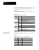
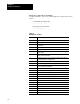
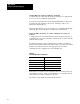
Table 7.D
Command
Block
Byte Meaning
1 & 2 number of bytes minus one to follow this word
3 & 4 no care byte and command byte
5 & 6 status byte (always zero) and tns byte (always zero)
7 & 8 tns byte (always zero) and function byte
9 thru n command data dependent on command & function
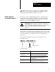
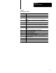
Table 7.E
Response
Block
Byte Meaning
1 & 2 no care byte and status byte (00 = success)
3 & 4 number of bytes to follow this word
5 & 6 command byte and status byte
7 & 8 tns word
9 thru n response data (stored low byte/ high byte)
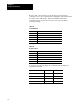
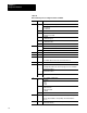
You can use the following diagnostic commands with the diagnostic
assignment command:
Command Command Byte Function Byte
Diagnostic Loop 06 00
Diagnostic Status 06 03
Diagnostic Read 06 01
Diagnostic Counters Reset 06 07