
User Manual PLC-3 FAMILY I/0 Instruction Manual

Diagnostics Methods
Chapter 7
7-16
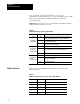
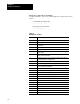
Table 7.H
Data
Sent in Response to a Diagnostic Status Command
Byte: Bit: Description:
1 Operating status of PLC-3 processor
0-1 00 = Program mode
01 = Test mode
10 = Run mode
2 Not used
3 0 = Normal
1 = Major processor fault
4 0 = Normal
1 = Shutdown request
5 0 = Normal
1 = Shutdown in effect
67 Not used
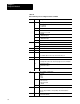
2 Type of station interface and processor
03 6 = scanner
47 4 = PLC-3 processor
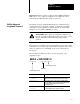
3 all Current context stored in bits 4 thru 7
4 all Thumbwheel
56 all Mode control word
The extended address of the mode control word is E0.0.0.8
78 all Starting byte address of the diagnostic counters.
9 Series and revision number of the module.
Even though the scanners are series A, they appear as series E modules
03 0 = Revision A scanner
1 = Revision B scanner
etc.
47 0 = Series A 1 = Series B
etc.
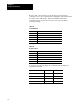
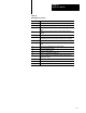
10 Type of channel communications
01 0 = Inactive
1 = DH
2 = DH+
3 = other
23 0 = A/G or earlier S5 or SR5
1 = A/H or later S5
2 = A/H or later SR5
3 = unused
47 unused
1114 all The physical address of the unused word of PLC-3 system memory.
This is the physical address corresponding to the extended address
E60.0.0.0
1518 all The total number of words in the PLC-3 system memory
(both used and unused)