
User Manual PLC-3 FAMILY I/0 Instruction Manual
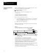

Scanner Hardware and Installation
Chapter 1
1-4
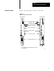
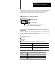
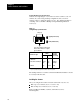
Pass and Fail Indicators
The indicators labeled PASS and FAIL (Figure 1.2) keep you informed
about the general condition of the scanner:
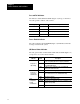
PASS (green) FAIL (red) Meaning
on off normal operation
off on module fault
on on powerup or system reset
off off system is not on or module has lost power
Forces Enabled Indicator
The yellow indicator labeled FORCE (Figure 1.2) illuminates when I/O
forcing is enabled in the system.
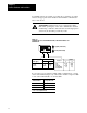
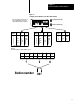
I/O Channel Status Indicators
The four green indicators labeled CH1, CH2, CH3, and CH4 (Figure 1.2)
correspond to one of the four I/O channels.
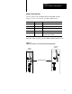
Indicator Status Description
CHx ON Communication between scanner module and the I/O chassis
on the corresponding I/O channel is properly established.
Configured for
I/O scanning
FLASHING There is a fault on one or more of the I/O chassis on the
corresponding I/O channel.
OFF No I/O chassis are configured on the corresponding I/O
channel or the channel is inactive.
CHx ON The channel is functioning properly.
Configured for
peertopeer
communication
FLASHING The input file is too small at the processor receiving data. The
slave or master does not exist. Communication retry.
OFF The channel is inactive.
CHx ON The channel is functioning properly.
Configured for
backup
communication
FLASHING The input file is too small at the processor receiving data. The
partner is not responding.
OFF The channel is inactive.