
User Manual PLC-3 FAMILY I/0 Instruction Manual


1000XXXX
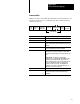
reset communications
reset response block seq cntr
reset command block seq cntr
set timeout value
Binary Command Language
Appendix A
A-4
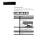
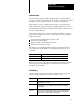
Circuit Control Request (CCR)
The master uses the circuit control request (CCR) to initiate, reset, or
verify communications with the scanner. The CCR consists of five bytes
of data defined as follows:
STX Control Code
Character
ChecksumTimeout Value ETX
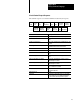
Command:
Description:
STX (start of text) the first byte of the control block (02 hex).
Control code In the control code byte, bits 7, 6, 5, and 4 contain the value 1, 0,
0, and 0 respectively. This is necessary for the scanner to
recognize the byte as a control code. The meaning of the other
bits in the control code is as follows:
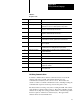
Character Timeout Value The third byte is the character timeout value. If bit 3 in the above
control code is set, this byte sets the character timeout value. The
timeout is 10 ms times the value in this byte, which allows timeout
values between 10 and 2550ms. If bit 3 in the control code is not
set, this byte is zero. A zero in this byte causes a default
character timeout as shown in Table A.A.
ETX (End of Text) 03 hex.
Checksum The fifth and last byte in the CCR is a checksum. The checksum
is the least significant eight bits of the sum of the previous four
bytes in the CCR.