
User Manual PLC-3 FAMILY I/0 Instruction Manual


Binary Command Language
Appendix A
A-5
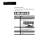
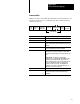
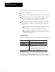
Circuit Control Request Response
The scanner response to a master’s CCR is a fourteen byte response.
STX RevSeries
Control
Code
Number
of
Bytes
Mod Type
and
thumbwheel
Max
command
block size
Max
response
block size
ETX
Current Character
Checksum
Current
command
block seq
response
block seq
timeout
value
Protocol
fault code
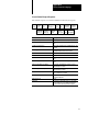
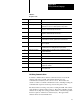
Command:
Description:
STX (start of text) the first byte of the control block (02 hex).
Control Code Value echoes the control code (byte two) of the
CCR.
Length of response block Count of the remaining bytes including this byte and
the ETX.
Module type and thumbwheel number Module type in the upper four bits and the
thumbwheel number in the lower four bits.
Scanner Series Scanner module's series number.
Scanner Revision Scanner module's revision number.
Maximum command block size Scanner module's maximum command block size in
bytes.
Maximum response block size Scanner module's maximum response block size in
bytes.
Current command block sequence The current command block sequence count as
maintained by the scanner.
Current response block sequence The current response block sequence count as
maintained by the scanner.
Character timeout value The character timeout value in 10's of ms. If zero
then see Table A.A for default.
Protocol fault code The protocol fault code. The possible fault codes
are listed in Table A.B.
ETX (End of text) 03 hex.
Checksum The last byte in the CCR response is a checksum.
The checksum is the least significant eight bits of
the sum of all the above bytes in the response.