
User Manual PLC-3 FAMILY I/0 Instruction Manual

Binary Command Language
Appendix A
A-15
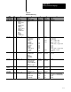
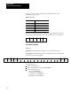
Table A.E
Extended
Addressing
Area E# .x .x .x .x .x
system status E0 context = 0 section = 0 word = 0 20 not used not used
module status E2 module type =
1 - memory
2 - main processor
3 - scanner
5 - communication
adapter
6 - expansion
7 - S4B I/O scanner
8 - peripheral
communication
9 - DH II
interface
14 - memory
communication
thumbwheel switch =
1 15
module data module data module data
data table E3 context = 1 15 section =
1 - output image
2 - input image
3 - timers
4 - counters
5 - integers
6 - floating point
7 - decimal
8 - binary
9 - ASCII
10 - high order int.
12 - pointers
13 - status
file =
0 999
0 999
0
0
0 999
0 999
0 999
0 999
0 999
0 999
0
0 999
structure =
0
0
0 9999
0 9999
0
0
0
0
0
0
0 9999
0
word =
0 07777 octal
0 07777 octal
0 CTL, 1 PRE, 2 ACC
0 CTL, 1 PRE, 2 ACC
0 9999
0 = lower 16 bits, 1 = upper 16 bits
0 9999
0 9999
0 9999
0 = lower 16 bits, 1 = upper 16 bits
0 = section/file, 1 = word
0 9999
ladder program E4 context = 1 15 section =
0 program status
1 main
2 subroutine
3 fault routine
rung =
0 32, 767
instruction =
0 32, 767
word =
0 32, 767
message E5 context = 1 15 section =
1 report generation
2 rung comments
3 terminal (MACROS)
4 DH
5 assistance (HELP)
message =
0 32, 767
word =
0 32, 767
not used
system
symbols
E6 context = 1 15 type = 1 symbol =
0 32, 767
word =
0 32, 767
not used
converted
procedures
E8 context = 1 15 section =
1 report generation
message =
0 32, 767
word =
0 32, 767
not used
force table E10 context = 1 15 force type =
0 status
1 forced output
2 forced input
rack =
not used
0 64
0 64
word = 0
0 15
0 15
bit =
0 input forces enabled/disabled
1 output forces enabled/disabled
not used
not used