
User Manual PLC-3 FAMILY I/0 Instruction Manual

Binary Command Language
Appendix A
A-20
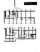
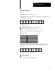
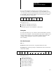
The following example command block uses the read I/O word command
to request the data and force information for the output word representing
rack 6, module group 4:
STX
02
ISC
01
SIZ
03
CMD
23 34
DAT
00
ETX
03
CHK
60
The data bytes store:
lower byte of the I/O address (34 hex)
upper byte of the I/O address (00 hex)
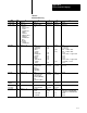
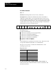
The processor responds to a read I/O word command with one of the
following response codes:
Response Codes
Hex Description
00 Success
03 Forces unavailable
04 Address unknown
06 Access not allowed
08 Address not complete
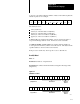
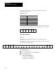
When the processor returns a success response, the data buffer also
contains the data stored at the requested address, and force-on and
force-off masks associated with that data. The following example shows a
response block for a read I/O word command when forces exist:
STX
02
OSC
01
SIZ
07
RSP
00 61 1C 02
CHK
92
DAT
86 80 00
ETX
03
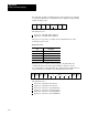
The data bytes store:
lower byte of the data word (61 hex)
upper byte of the data word (1C hex)
lower byte of the force-on mask (02 hex)
upper byte of the force-on mask (86 hex)
lower byte of the force-off mask (80 hex)
upper byte of the force-off mask (00 hex)