
User Manual PLC-3 FAMILY I/0 Instruction Manual

Binary Command Language
Appendix A
A-24
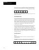
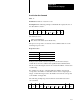
When the processor receives a read-modify-write command,
it (Figure A.3):
1. Reads the data at the specified address.
2. Performs a logical AND operation between the data read in step 1 and
the AND mask.
3. Performs a logical OR operation between the result of step 2 and the
OR mask.
4. Writes the result of step 3 into the word at the specified address.
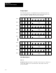
Figure A.3
ReadModifyWrite
Operation
Bit Pattern Description
1111000011110000 Initial state of specified word
0101010101010101 AND mask
0101000001010000 Result of logicalAND operation
1010000001011111 Final result
The processor responds to a read-modify-write command with one of the
following response codes:
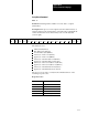
Response Codes
Hex Description
00 Success
04 Address unknown
06 Access not allowed
08 Address not complete
0F No privilege
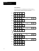
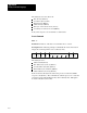
The following response block shows a successful read-modify-write
command:
STX
02
OSC
01
SIZ
01
RSP
00
ETX
03
CHK
07