
User Manual PLC-3 FAMILY I/0 Instruction Manual

Scanner Hardware and Installation
Chapter 1
1-10
Setting Backup System Functions
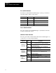
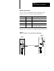
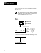
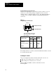
On the bottom edge (Figure 1.7) near the rear of the scanner is a set of 4
switches. If you are using a backup configuration, then you can set
switches 2 and 3 to define the switchover type. For detailed information
on backup, refer to the PLC-3 Backup Concepts Manual (publication
1775-6.3.1).
Figure 1.7
Setting
Backup System Functions
switchback
If you are operating a backup system,
then set these switches to set up the
type of switchover.
Switchover Type
Switch
23
Auto with controllable
Auto with no switchback
down up
Manual
down
up
up
up
up
down
both
primary
backup
both
System
(primary
or backup)
1
If you are not operating a backup system, then set switches 2 and 3 to the UP position.
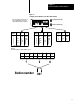
1234
Always Up
Up (away from board)
Down (toward board)
The backup switches for scanners other than thumbwheel number 1 should
be set away from the board.
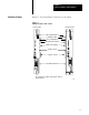
Installing the Scanner
After you configure the scanner, insert the scanner into any slot of a:
PLC-3 processor chassis (cat. no. 1775-A1, -A2)
PLC-3/10 processor chassis (cat. no. 1775-A3)
PLC-3 and PLC-3/10 CPUs, scanners, and memories are not
interchangeable.