
User Manual PLC-3 FAMILY I/0 Instruction Manual

Scanner Hardware and Installation
Chapter 1
1-15
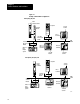
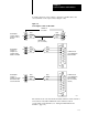
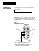
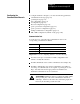
To make connections to the scanner, connect the 1770-CD cable to the
screw terminals on the 3-pin connector (Figure 1.10).
Figure 1.10
Connecting
the Scanner to a DH or DH+
1 2 34 5678
9101112131415
Connecting the
scanner to another
scanner on a DH or
DH+ link
Connecting the
scanner to a
computer via a
computer interface
module on a DH link.
Connecting the
scanner to a
computer via a Series
B 1770KF2 module
on a DH or DH+ link.
1 2345678
9101112131415
Terminals on
the scanner
Twinaxial Cable
(cat. no. 1770CD)
Clear
Shield
Blue
1
SH
2
1
SH
2
Clear
Shield
Blue
Clear
Shield
Blue
Clear
Shield
Blue
Clear
Shield
Blue
Clear
Shield
Blue
1
SH
2
1
SH
2
15Pin Connector
on a Communication
Interface Module
15Pin Connector
on a Communication
Interface Module
(cat. no. 1770KF2,
series B)
15408
The scanner has an on-board switch-selectable terminator. If the scanner is
an end device in the DH or DH+ link, set the terminator switch
corresponding to I/O channel 4 (see “Setting the Thumbwheel and
Switches,” page 1-6).