Allen Bradley PLC 3 Family Programmable Controllers product icon Quick Start for Experienced Users
Important User Information Because of the variety of uses for the products described in this publication, those responsible for the application and use of this control equipment must satisfy themselves that all necessary steps have been taken to assure that each application and use meets all performance and safety requirements, including any applicable laws, regulations, codes and standards.
Table of Contents Overview . . . . . . . . . . . . . . . . . . . . . . . . . . . . . . . . . . . . . . P-1 Using this Quick Start . . . . . . . . . . . . . . . . . . . . . . . . . . . . . . . . . What You Need to Do . . . . . . . . . . . . . . . . . . . . . . . . . . . . . . . . . System Components used in this Quick Start . . . . . . . . . . . . . . . . If You Need Help ... . . . . . . . . . . . . . . . . . . . . . . . . . . . . . . . . . .
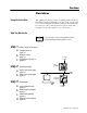
Preface Overview Using this Quick Start This quick start is designed to help you quickly install and connect a basic PLC-3 family programmable controller system. Use this guide if you are knowledgeable about PLC-3 family products but may not have used one or more of the products for a period of time. The information we provide is geared to “jog your memory.” What You Need to Do For more information...
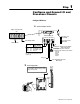
P–2 Overview step 4 a b step 5 Install and Connect I/O Install and wire I/O modules (page 5 1) Connect I/O to scanner (page 5 2) Configure and connect a programming terminal (page 6 1) System Components used in this Quick Start Publication 1775 10.
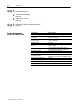
Overview If You Need Help ... A B P–3 If you need additional assistance in installing or connecting your PLC-3 family programmable controller system, start with the troubleshooting section in the appendix of this quick start. If you still experience difficulty, call 1-800-9NEWLIT to order one of the publications suggested below or contact your Allen-Bradley service representative. Publication title: Publication number: PLC 3 Programmable Controllers Installation and Operation Manual 1775 6.7.
Step 1 Configure and Ground I/O and Processor Chassis Configure I/O Chassis a Set the backplane switches.
1–2 Configure and Ground I/O and Processor Chassis Configure Processor Chassis Set the backplane switches located near the upper left hand corner of the chassis backplane.
Step 2 Install Power Supply a Install 1775 P3 Power Supply into the PLC 3/10 (or single chassis PLC 3) Install the dc power cable. PLC 3/10 chassis Feed the dc power cable under the module guides along the backplane. CF2 backplane CF1 Squeeze the side tabs of the plugs as you connect them to the backplane.
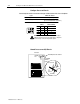
2–2 Install Power Supply c Set the voltage switch for the proper range. 115V ac operation 230V ac operation Selector Switch Selector Switch 230V 230V 115V 115V Terminal Strip L1 L2/N GND N.C. COM. N.O. L1 N 115V AC Terminal Strip L1 230V AC L2 L1 L2/N GND N.C. COM. N.O. 20419 M ! ATTENTION: Be sure to set the voltage selection switch properly or you may damage the power supply module.
Install Power Supply 2–3 Install 1775 P1 Power Supply into the PLC 3 a Connect the 1775 CAP chassis power cable to the processor chassis. b Optionally, connect the I/O chassis to the power supply using an I/O power cable. We do not recommend this connection for backup system configurations. Power Cable c Make AC power connections. L2 220/240V ac L1 L2 120V ac L1 Jumpers (a) 120V ac Operation Jumper (b) 220/240V ac Operation Publication 1775 10.
Step 3 Install Processor, Memory, and Scanner Modules Connect Front Panel Cable and Install Processor Install the processor in the first slot on the left of the chassis for the best heat dissipation. You must install the processor in the chassis numbered 0 if you are using expansion chassis. Install Memory Module(s) (for PLC 3 processor only) a Remove power to the processor chassis.
3–2 Install Processor, Memory, and Scanner Modules Install I/O Scanner Module(s) ! a ATTENTION: Do not change the thumbwheel setting on a scanner while power is on or equipment damage may result. Set each thumbwheel switch to a unique number between 1 and 15. You must have a scanner with the thumbwheel set for 1. If you are installing a multiple chassis PLC 3 system, the scanner module whose thumbwheel you set to 1 must be in the chassis with the front panel.
Step 4 Install, Wire, and Connect I/O Install and Wire I/O Modules For more information... Specific wiring information for each type of I/O module is contained in the product data publication for that specific module. Therefore, refer to the appropriate product data publication when you follow these steps. a Open each module locking bar and insert each I/O module into the slot keyed for it. After you install each module group, secure the modules in place with the module locking bar.
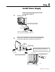
4–2 Install, Wire, and Connect I/O Connect I/O Connect the I/O scanner to the RIO adapters. Channel No. 3 Channel No.1 I/O Scanner Module Swing Arm Terminator (Cat. No. 1770-XT) Blue Shield Clear Line 1 Shield Lin 2 Line 1 Shield Lin 2 Line 1 Shield Line 1 Shield Lin 2 Lin 2 Channel No.2 I/O Adapter Module Field Wiring Arm Twinaxial Cable (Cat. No.
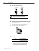
Step 5 Configure a Personal Computer Configure and Connect 1770 T4 Programming Terminal a Remove the keyboard from the industrial terminal and locate the switch assembly on the front of the terminal. b Set the terminal switches. Set switches 4 and 5 to the UP position. c Connect terminal to processor using a 1775 CAT cable. PLC-3 Processor Front Panel CH0 or 1775-S4A Module CH 5 Industrial Terminal System (Cat. No. 1770-T4) 25-pin Male Connector with Right-Angle Hood Cat. No.
5–2 Configure a Personal Computer Connect to Personal Computer 42 21 62 1 43 1784 CP3 Interconnect Cable 320.04 cm (126") 22 1 14 23 3 24 18 2 25 1 Using 6200 Programming Software For more information... For specific information about using 6200 programming software, see the PLC 3 Programming Software Configuration Manual, publication 6200 6.4.16.
Appendix Troubleshooting and Specifications Power supply Module Indicators If you don’t see the power-supply module indicators lit as specified on page 3-2, use the following table to troubleshoot the problem.
A–2 Troubleshooting and Specifications Specifications for PLC-3/10 processors follow. PLC 3/10 System Dimensions G 19 by 20 by 14.5¨ (483by508 by 368 mm) mainframe and power supply Mounting G Panel or 19 inch rack mount I/O Capacity (per system) G 2048 inputs and outputs (total, any mix) G 2048 inputs and 2048 outputs (total, complementary) G 2 scanners (max) Scan Time (nominal) G 1 ms per 1K words of relay type instructions G 2.
I–2 Publication 1775 10.1 - March 1996 Supercedes 1775 2.20 August 1988, 1775 5.1 March 1995, 1775 2.4 November 1985, 1775 2.26 July 1988 Publication 1775 10.1 - March 1996 PN 955124 60 Copyright 1996 Allen Bradley Company, Inc.