Allen Bradley Data Highway II/Data Highway Plus Interface Module (Cat. No.
Table of Contents Using This Manual . . . . . . . . . . . . . . . . . . . . . . . . . . . . . . . 1 1 Chapter Objectives . . . . . . . . . . . . . . . . . . . . . . . . . . . . . . . . . . . Purpose of This Manual . . . . . . . . . . . . . . . . . . . . . . . . . . . . . . . Who Should Read This Manual . . . . . . . . . . . . . . . . . . . . . . . . . . Precautionary Notes . . . . . . . . . . . . . . . . . . . . . . . . . . . . . . . . . . Frequently Used Terms . . . . . . . . . . . . . . . . . . . . . .
ii Table of Contents Addressing from Data Highway Plus . . . . . . . . . . . . . . . . . 5 1 Chapter Objectives . . . . . . . . . . . . . . . . . . . . . . . . . . . . . . . . . . . Limitations on Sending Commands . . . . . . . . . . . . . . . . . . . . . . . Addressing a Local Data Highway II Node Using Local Addressing . Communicating to a Remote Data Highway II Using Remote Addressing . . . . . . . . . . . . . . . . . . . . . . . . . . . . . . .
Chapter 1 Using This Manual Chapter Objectives After reading this chapter, you should know: Terminology Used throughout This Manual Where to Locate Information On Related Products Purpose of This Manual This manual describes the Data Highway II/Data Highway Plus Communication Adapter Module (Cat. Nos. 1779-KP5, -KP5R).
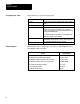
Chapter 1 Using This Manual Frequently Used Terms In this manual, we use the following terms: This Term: Means: 1779 KP5 Both the 1779 KP5 and 1779 KP5R modules unless otherwise noted. Data Highway Plus Formerly the Peer Communications Link (PCL) Node The point at which devices, such as programmable controllers, interface to the network. Usually, the node is an interface module (except for the PLC 5 and T50 terminal which connect directly to Data Highway Plus).
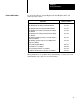
Chapter 1 Using This Manual Related Publications For more information on Data Highway II, Data Highway Plus, and related products, refer to: Publication Publication Number Data Highway II Overview Product Data 1779 2.10 Data Highway Cable Assembly and Installation Manual 1770 6.2.1 Data Highway II Cable Assembly and Installation Manual 1779 6.5.7 Data Highway II PLC 2 Family (1779 KP2) Interface Module User's Manual 1779 6.5.
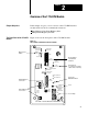
Chapter 2 Overview of the 1779 KP5 Module Chapter Objectives In this chapter, we give you an overview of the 1779-KP5 interface module and how it allows communication between: Data Highway II and Data Highway Plus Multiple Data Highway II Links The Front Panel of the 1779 KP5 Module Figure 2.1 shows the front panel of the 1779-KP5 module. Figure 2.
Chapter 2 Overview of the 1779 KP5 Module Figure 2.2 shows the front panel of the 1779-KP5R module with the redundant cabling option. Figure 2.
Chapter 2 Overview of the 1779 KP5 Module For More Information on: Refer to: Making Connections and Setting Switches on the 1779 KP5 Chapter 3 Using the LED Diagnostic Indicators Chapter 6 Data Highway II Redundant Cabling The Data Highway II Cable Planning and Installation Manual (Publication 1779 6.5.7) Using the 1779 KP5 on Your Network Figure 2.3 shows an example configuration of a network using the 1779-KP5. Figure 2.
Chapter 2 Overview of the 1779 KP5 Module Connecting Data Highway Plus to Data Highway II Figure 2.4 shows an example of using a 1779-KP5 to connect a Data Highway Plus link to a Data Highway II link. Figure 2.
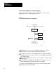
Chapter 2 Overview of the 1779 KP5 Module Connecting Two Data Highway II Links Figure 2.5 shows an example of using two 1779-KP5 modules as a bridge between two Data Highway II links. Figure 2.5 Connecting Two Data Highway II Links Data Highway II 1779 KP5 1779 KP5 Data Highway II Data Highway Plus (Do not attach nodes when used in bridge configuration.) Assigning Link Numbers 16483 You must assign a link number to each link on your network (Figure 2.6).
Chapter 2 Overview of the 1779 KP5 Module You cannot connect nodes to Data Highway Plus links that are part of a bridge configuration. Also, make sure that both 1779-KP5 modules in a bridge configuration assign the same link number to the Data Highway Plus link. You can also assign a link number to a Data Highway Plus link that is not part of a bridge configuration.
Chapter 2 Overview of the 1779 KP5 Module on Link 10 know that in order to reach a device on Link 8, they must route the message through Node 20. Node 20 also broadcasts its route update message to Node 30. Node 30 broadcasts the message to Series B modules on Link 8. This tells the Series B modules on Link 8 that in order to reach a device on Link 10, they must route the message through Node 30.
Chapter 3 Installing the 1779 KP5 Module Chapter Objectives This chapter provides procedures for: Mounting the 1779-KP5 Setting the Data Highway II Node Address for the 1779-KP5 Setting Option Switches on the 1779-KP5 Connecting Communication Cables to the 1779-KP5 Connecting Power and Ground to the 1779-KP5 Powering Up the 1779-KP5 Guidelines for Mounting the 1779 KP5 You mount the 1779-KP5 in an enclosure.
Chapter 3 Installing the 1779 KP5 Module Figure 3.1 Example of Minimum Spacing for Necessary Air Flow 4” 6” 1 4” 6” 4” 6” 6” 4” 6” 1 The temperature of the air must not exceed 60°C (140°F) at any point immediately below any chassis. This may limit how high chassis can be mounted in an enclosure.
Chapter 3 Installing the 1779 KP5 Module Figure 3.2 shows the mounting dimensions for the 1779-KP5 interface. Figure 3.2 Mounting Dimensions 3.8 in (97 mm) Use 0.25 in. mounting bolts (3 places) 1.9 in. (48mm) 14.25 in. (362 mm) 15.25 in. (387 mm) 6.5 in. (165 mm) Clearance depth including cable connectors is 11 inches (280 mm). 16008 Drill and tap the three holes in the enclosure back panel for mounting the module. Insert the mounting bolt into the bottom hole.
Chapter 3 Installing the 1779 KP5 Module Setting the Node Address Set the node address for your module using the three thumbwheels on the front panel of your module (Figure 3.3). Figure 3.
Chapter 3 Installing the 1779 KP5 Module There are three sets of switches (labeled S-2, S-4, and S-5) on the 1779-KP5 host board. Use the following procedure to access these switches: CAUTION: Electrostatic discharge can degrade performance or cause permanent damage to the module. To minimize or prevent electrostatic discharge damage, handle the module at a static-safe workstation.
Chapter 3 Installing the 1779 KP5 Module 3. After you finish setting switches, push the removable frame back to the operating position and tighten the four fasteners on the front of the module. The fasteners must be tight to ensure that AC power is not interrupted by the interlock switch on the power-supply board. Figure 3.4 shows the switch-setting label on the side of the 1779-KP5. Figure 3.
Chapter 3 Installing the 1779 KP5 Module Switch Assembly S 2: Link Address You use Switch Assembly S-2 to set a unique link address (between 1 and 15) for both the Data Highway II and Data Highway Plus links connected to the 1779-KP5 in a bridge configuration. The 1779-KP5 uses these link addresses to route messages. Refer to the following table: If You Are Using: Then: A 1779 KP5 in a Bridge Configuration to Connect Two Data Highway II Links You need to assign link addresses (using DIP switches).
Chapter 3 Installing the 1779 KP5 Module For example, to set a Data Highway Plus link address of 5 and a Data Highway II link address of 6, you would set the switches as follows: 1 3 2 4 5 6 7 8 OPEN 1+4 2+4 5 6 16499 Switch Assembly S 4: Enable/Disable Route Update You use Switch Assembly S-4 to enable or disable the route update message on your network. 1 3 2 4 When you press a switch towards the word OPEN, you turn the switch ON.
Chapter 3 Installing the 1779 KP5 Module Switch Assembly S 5: Data Highway Plus Communication Rate You use the set of switches labeled S-5 to set the Data Highway Plus communication rate. You must set both these switches ON (toward the word OPEN) for a communication rate of 57.6 Kbits per second. 1 2 OPEN Set both switches ON (toward the word OPEN) for 57.6K baud. Set Switch 1 ON and Switch 2 OFF for 115.2K baud. (This setting can be used only when you are using two modules in bridge mode.
Chapter 3 Installing the 1779 KP5 Module 115V Push switch down for 230V operation. Setting the Data Highway Plus Terminating Resistor 3. Set the voltage-selection switch to correspond to the level (115V/230V) of your AC power source. The module is factory set to 115V AC. 4. Push the removable frame back to the operating position and tighten the four fasteners on the front of the module.
Chapter 3 Installing the 1779 KP5 Module CAUTION: Electrostatic discharge can degrade performance or cause permanent damage to the module. To minimize or prevent electrostatic discharge damage, handle the module at a static-safe workstation. If a static-safe workstation is not available, touch and remain in contact with a grounded object to discharge yourself while handling the module. 1. Make sure that you remove all power to the module.
Chapter 3 Installing the 1779 KP5 Module 3. Connecting Communication Cables After you finish setting the resistor, push the removable frame back to the operating position and tighten the four fasteners on the front of the module. The fasteners must be tight to ensure that AC power is not interrupted by the interlock switch on the power-supply board. After you have set the switches and the terminator, you can connect the communication cables necessary for your application.
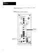
Chapter 3 Installing the 1779 KP5 Module Figure 3.5 Connections to the Networks on the 1779 KP5 DC POWER ON AC POWER ON DH II AUX ACCESS ON AC POWER OFF 1784-T50 Connector FUSE DATA HWY II PORT 1 DATA HWY PLUS SLOW BLOW 2A, 250V 115V AC/230V AC INTERNALLY SWITCH SELECTABLE L1 L2/N GND Data Highway II Connector Data Highway Plus Connector CAT. NO.
Chapter 3 Installing the 1779 KP5 Module Connecting a T50 Industrial Terminal You can connect a T50 Industrial Terminal (Cat. No. 1784-T50) to the 1779-KP5 for use on the Data Highway Plus network. To connect the T50 to the 1779-KP5, you can use a 1784-CP5 cable, or you can construct a cable using the following pinout: User-Supplied Cable Belden 9463 or Equivalent (10 Ft. Max.
Chapter 3 Installing the 1779 KP5 Module To provide AC power isolation between the 1779-KP5 and other equipment, connect a separate transformer between the module’s power supply and the AC power source. Connect the: Transformer primary to the AC source. High side of the transformer secondary to the L1 terminal of the power supply. Low side of the transformer secondary to the L2/N terminal of the power supply. The 1779-KP5 consumes 50 watts of power.
Chapter 3 Installing the 1779 KP5 Module 2. Connect the GND post on the module to the central ground bus of your enclosure. 115V AC/230V AC INTERNALLY SWITCH SELECTABLE Green Grounding Conductor L1 Central Ground Bus of Enclosure L2/N GND Earth Ground INTERFACE GND Post 16014 The interface is shipped to you with a wire connecting the post to the stationary frame and another wire connecting the post to the GND terminal of the terminal block.
Chapter 3 Installing the 1779 KP5 Module Powering Up the 1779 KP5 Interface To power up the 1779-KP5, use the following procedure: 1. Set the AC POWER switch on the front panel of the module to OFF. AC POWER ON AC Power Switch ON AC POWER OFF SLOW BLOW 2A. 250V FUSE DATA HWY II PORT 1 115V AC/ 230V AC INTERNALLY SWITCH SELECTABLE L1 L2/N DATA HWY II PORT 2 GND 1779-KP5R DHII/DH+ INTERFACE 16015 2. Restore power to the 1779-KP5.
Chapter 4 Addressing from Data Highway II Chapter Objectives In this chapter, we provide a description of how to address the following links from a node on Data Highway II: A Data Highway Plus Link Using Local Link Addressing (Link = 0) Another Data Highway II Link Using Remote Link Addressing (Link > 0) A Data Highway Plus Link Using Remote Link Addressing (Link > 0) Limitations on Sending Commands The 1779-KP5 does not support Data Highway II time-critical commands because these commands are not sup
Chapter 4 Addressing from Data Highway II Addressing a Data Highway Plus You use local addressing to communicate with a node on a local Data Node Using Local Addressing Highway Plus link. A local Data Highway Plus link: Is directly connected to the Data Highway II link you are communicating from. Has a link value of zero. Figure 4.1 shows an example of a configuration which uses local addressing. Figure 4.
Chapter 4 Addressing from Data Highway II The NODE value for each Data Highway Plus node is the same as the node address of the 1779-KP5 it is connected to (between 01 and 77 octal). Refer to Chapter 3 for information on setting the node address of a 1779-KP5 using the thumbwheels on the front panel. For example, if the NODE value of the 1779-KP5 is 50 (octal), the NODE value of each Data Highway Plus node connected to it is also 50. The USER value is the Data Highway Plus node address.
Chapter 4 Addressing from Data Highway II Addressing Data Highway Plus from a PLC 2 To send a message from a PLC-2 (1779-KP2) on Data Highway II to a Data Highway Plus node, you use the following address format in the communication zone of your ladder-logic program (NNN = Node, UUU = User): NNN UUU = The 1779-KP2 does not support the network layer. The LINK value is automatically 00 (local link).
Chapter 4 Addressing from Data Highway II Addressing Data Highway Plus from a PLC 3 To send a message from a PLC-3 (1779-KP3) on Data Highway II to a Data Highway Plus node, you use the following address format in the message instruction of your ladder-logic program (NNN = Node, UUU = User): :NNN.UUU The 1779-KP3 does not support the network layer. The LINK value is automatically 00 (local link).
Chapter 4 Addressing from Data Highway II Important: If you use a file value of greater than 15, the value wraps around to zero. For example, a value of 16 specifies File 0, a value of 17 specifies File 1, etc. You must enter the PLC-5 address in the following address format: $ E [Major Section] . [File #] . [Element] . [Sub-Element] If you send a full PLC-3 six-level address to a PLC-5, the PLC-5 will return an error.
Chapter 4 Addressing from Data Highway II A computer with Data Highway (DF1) driver connected to a 1779-KFL in KE/KF emulation mode will only be able to address a single Data Highway Plus node. This Data Highway Plus node must have a Data Highway Plus address of 002.
Chapter 4 Addressing from Data Highway II When you send a message from a node on your Data Highway II link to a node on a remote Data Highway II link, you address the node using the LINK, NODE, and USER fields. Use the LINK field to specify what link the remote node is on. The LINK value of a remote link can be between 1 and 15. You set the link value of a remote link using switches on the remote link’s 1779-KP5 (Chapter 3). Use the NODE and USER fields the same way as normal Data Highway II addressing.
Chapter 4 Addressing from Data Highway II Figure 4.3 Remote Addressing Configuration Data Highway II Sending Node 1779 KP5 1779 KP5 Data Highway II 1779 KP5 Data Highway Plus (Do not attach nodes when used in bridge configuration.) PLC 5 Data Highway Plus PLC 5 1784 T50 16490 There are two ways to communicate to a remote Data Highway Plus link: Using a Remote Data Highway II Link Number Using a Remote Data Highway Plus Link Number The following sections show these two methods.
Chapter 4 Addressing from Data Highway II Figure 4.4 Addressing a Remote Data Highway Plus Node Using a Data Highway II Link Number Link = 01 Data Highway II Sending Node Link = 02 1779 KP5 Link = 03 1779 KP5 Data Highway Plus (Do not attach nodes when used in bridge configuration.
Chapter 4 Addressing from Data Highway II Using a Data Highway Plus Link Number When you use a Data Highway Plus link number, you can address up to 64 nodes to your Data Highway Plus link. To use a Data Highway Plus link number to address a Data Highway Plus node, you must: Not enable the route update messages. This means that your 1779-KP5 can receive route updates, but it cannot send a route update to inform other 1779-KP5 modules on where to find the Data Highway Plus link.
Chapter 4 Addressing from Data Highway II The LINK number is the LINK number you have set on your 1779-KP5 for the Data Highway Plus link (Chapter 3). The NODE number is the destination node’s Data Highway Plus address. The USER number must be 1.
Chapter 5 Addressing from Data Highway Plus Chapter Objectives In this chapter, we provide a description of how to address nodes on: Data Highway II from nodes from Data Highway Plus. Another Data Highway Plus connected to the same Data Highway II network. Another Data Highway Plus connected to a remote Data Highway II network.
Chapter 5 Addressing from Data Highway Plus Figure 5.1 Data Highway II and Data Highway Plus Configuration Data Highway II 1779 KFL 1779 KP5 PLC 5 Data Highway Plus 1784 T50 PLC 5 16493 When you send a message to a Data Highway II node from Data Highway Plus, you specify the address using the LINK, NODE, and USER fields the same way as the normal Data Highway II addressing. The LINK value for local addressing is always zero.
Chapter 5 Addressing from Data Highway Plus You can send commands to Data Highway II from Data Highway Plus Addresses 002 through 020 (octal). You may still assign Address 001 (the default address for the 1784-T50) and Addresses 021 through 077 (octal) on your Data Highway Plus network, but these nodes are unable to initiate messages to nodes on your Data Highway II network. In our examples, we use a 1784-T50 Industrial Terminal and Version 2.2 software to display PLC-5 commands.
Chapter 5 Addressing from Data Highway Plus Data Highway Plus to a PLC 3 (1779 KP3, KP3R) The following example shows a PLC-5 message instruction that reads 100 words of data from a PLC-3 (Data Highway II Link 00, Node 11), starting at Memory Location B100:0. The command stores the data at Memory Location N100:0 in the initiating PLC-5.
Chapter 5 Addressing from Data Highway Plus Data Highway Plus to a Synchronous Device Interface (1779 KFM, KFMR) The following example shows a PLC-5 message instruction (displayed by the T50) that writes 100 words of data from the PLC-5, starting at Memory Location N100:0. The command is a PLC-2-type command and stores the data at Memory Offset 010 in the computer.
Chapter 5 Addressing from Data Highway Plus Data Highway Plus to an Asynchronous Device Interface (1779 KFL, KFLR) The following is an example of PLC-5 message instruction that writes 100 words of data from the PLC-5, starting at Memory Location N100:0, to the first port (USER = 01) of the 1779-KFL. The command is a PLC-2-type command and stores the data at Memory Offset 010 in the computer.
Chapter 5 Addressing from Data Highway Plus Figure 5.2 Data Highway Plus to Remote Data Highway II Configuration Data Highway II 1779 KP5 1779 KP5 PLC 5 Data Highway Plus 1779 KP5 Data Highway Plus (Do not attach nodes when used in bridge configuration.) Data Highway II 1779 KFL PLC 5 1784 T50 16494 The LINK value is the link value of the remote Data Highway II link. You set this number with switches on the 1779-KP5 (refer to Chapter 3).
Chapter 5 Addressing from Data Highway Plus Communicating to a Local Data Highway Plus Link Using Local Addressing Two Data Highway Plus links are considered local to each other if they are connected to the same Data Highway II link. Figure 5.3 shows an example configuration using local Data Highway Plus links. Figure 5.
Chapter 5 Addressing from Data Highway Plus words from Memory Location N100:0 of the remote PLC-5 and stores them in Memory Location N100:0 in the initiating PLC-5.
Chapter 5 Addressing from Data Highway Plus Figure 5.4 A Remote Data Highway Plus Configuration Link = 01 Link = 02 Data Highway II 1779 KP5 Link = 00 Node = 50 User = 01 PLC 5 Data Highway Plus 1784 T50 1779 KP5 PLC 5 Link = 00 Node = 50 User = 20 1779 KP5 Data Highway Plus (Do not attach nodes when used in bridge configuration.
Chapter 5 Addressing from Data Highway Plus MESSAGE INSTRUCTION DATA ENTRY FOR CONTROL BLOCK N13:0 Read/Write: PLC-5 Data Table Address: Size in Elements: Local/Remote: Remote Station: Link ID: Remote Link Type: Local Node Address: Processor Type: Destination Data Table Address: BLOCK SIZE = 11 WORDS READ N100:0 1000 REMOTE Node = 055 User = 013 03 DATA HIGHWAY II 50 PLC-5 N100:0 Press a key to change a parameter or to accept parameters.
Chapter 5 Addressing from Data Highway Plus Figure 5.5 A Remote Data Highway Plus Configuration Link = 01 Link = 02 Data Highway II 1779 KP5 Link 04 1779 KP5 Link = 01 Node = 50 User = 01 PLC 5 Link = 04 Node = 20 User = 01 1779 KP5 Data Highway Plus (Do not attach nodes when used in bridge configuration.
Chapter 5 Addressing from Data Highway Plus MESSAGE INSTRUCTION DATA ENTRY FOR CONTROL BLOCK N13:0 Read/Write: PLC-5 Data Table Address: Size in Elements: Local/Remote: Remote Station: Link ID: Remote Link Type: Local Node Address: Processor Type: Destination Data Table Address: BLOCK SIZE = 11 WORDS READ N100:0 1000 REMOTE Node = 013 User = 001 05 DATA HIGHWAY II 50 PLC-5 N100:0 Press a key to change a parameter or to accept parameters.
Chapter 6 1779 KP5 Troubleshooting Tools Chapter Objectives In this chapter, we provide information on: Replacing circuit boards in your 1779-KP5. Using LED indicators on the front of the 1779-KP5. Using the 1779-KP5 diagnostic status bytes and a list of the status information. Using the 1779-KP5 diagnostic counters and a list of the counters. Error codes that may be sent to your node when communicating with the 1779-KP5.
Chapter 6 1779 KP5 Troubleshooting Tools This Board: Catalog Number: Power Supply MAC Host 1779 PH2 1779 JMA/1779 JMAR 1779 JP5 Provides a Link to: The Power Source for Your Module The Data Highway II Network The Data Highway Plus Network The Power-Supply Board and MAC board are the same boards that you use for the other Data Highway II modules (except the 1779-KP3). This means that you do not need to keep a different type of spare Power-Supply Board or MAC board for each interface on your network.
Chapter 6 1779 KP5 Troubleshooting Tools The 1779-KP5 has 19 indicators on its front panel.
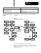
Chapter 6 1779 KP5 Troubleshooting Tools When the module is passing the token or sending messages on a small network, the RECEIVE LED appears to remain lit and the TRANSMIT LED flickers. Using the LEDs to Troubleshoot the Module When you suspect that the 1779-KP5 is not functioning properly, use the following troubleshooting flowchart (Figure 6.3). Figure 6.
Chapter 6 1779 KP5 Troubleshooting Tools 1779 KP5 Diagnostic Status Bytes Diagnostic status bytes contain information about the module, Data Highway II, and Data Highway Plus. To read the status bytes, you send a Diagnostic Status command from a computer on your Data Highway II or Data Highway Plus network. For information on how to read diagnostic status bytes, refer to the Data Highway/Data Highway Plus Protocol and Command Set Reference Manual (Publication 1770-6.5.16).
Chapter 6 1779 KP5 Troubleshooting Tools Diagnostic Status Bytes for Data Highway Plus Data Highway Plus diagnostic status bytes can be read from an intelligent device (computer) connected to your Data Highway Plus network.
Chapter 6 1779 KP5 Troubleshooting Tools 1779 KP5 Diagnostic Counters The following sections tell you: What a Diagnostic Counter Is How to Read Diagnostic Counters What 1779-KP5 Diagnostic Counters Contain What is a Diagnostic Counter? A diagnostic counter records an event of interest for debugging the module and for longer term reliability analysis. Since Data Highway II uses application layer diagnostic counters, the 1779-KP5 does not have diagnostic counters for Data Highway II.
Chapter 6 1779 KP5 Troubleshooting Tools You can then use this information to format a Diagnostic Read command. The reply from the Diagnostic Read command contains the data stored in the counters. For more information on the Diagnostic Status and Diagnostic Read commands, refer to the Data Highway/Data Highway Plus Protocol and Command Set Reference Manual (Publication 1770-6.5.16). 1779 KP5 Data Highway Plus Diagnostic Counters The 1779-KP5 stores 28 Data Highway Plus counters in 35 bytes.
Chapter 6 1779 KP5 Troubleshooting Tools 1779 KP5 Error Codes When you send a message to a 1779-KP5, it may return one of the errors listed in the table below. The error code will be returned in the EXT STS byte of a packet. Error Code: Is Returned When: 90 NO_MEM The Data Highway Plus node that you addressed has no memory to buffer the message. F7 ERR_BAD_USER The Data Highway Plus node that you addressed is not an active node.
Appendix A Specifications Function Interface a Data Highway Plus network with a Data Highway II network. Communication Ports Data Highway II: BNC Connector Data Highway Plus: 3-Screw Terminal Block 1784-T50 Terminal: 9-Pin Male D-Shell Connector DHII AUX ACCESS Connector: For Future Product Enhancement (Keep covered with conductive cap provided to avoid electrostatic discharge.) Communication Rates Data Highway II: 1 Mb Data Highway Plus: 57.6 Kb, 115.
Appendix B Using 6200 Series Software Version 2.1 and Earlier Version 2.
Appendix B Using 6200 Series Software Version 2.1 and Earlier The following table tells you what information you must enter at each prompt: At This Prompt: You: Read/Write Toggle between READ for a read command and WRITE for a write command. PLC 5 Data Table Address Enter the local data table address where data starts for the WRITE command or data will be stored for the READ command. Size in Elements Enter the message size in elements. Local/Remote Select REMOTE (through the 1779 KP5).
Appendix B Using 6200 Series Software Version 2.1 and Earlier Entering the User Number into the Message Control File When you use 6200 Series software Version 2.1 (or earlier) to communicate from a node on Data Highway Plus to a: computer/1779-KFL on Data Highway II node on a remote Data Highway Plus network you must manually enter the USER number into the message control file.
Appendix B Using 6200 Series Software Version 2.1 and Earlier 3. Determine the location of the USER number byte based on the following information.
Appendix B Using 6200 Series Software Version 2.1 and Earlier During the Change: Address 0 1 2 3 4 5 6 7 8 9 N13:0 N13:10 0000 2728 0064 0407 0064 0000 000B 0002 1000 0400 0000 Press a key or enter value.
Index A Address - Setting the 1779-KP5 Address, 3 4 Addressing - Data Highway II to a Local Data Highway Plus Node, 4 2 Remote Data Highway II Node, 4 7 Remote Data Highway Plus Node, 4 8 Addressing - Data Highway Plus to a Local Data Highway II Node, 5 1 Local Data Highway Plus Node, 5 8 Remote Data Highway II Node, 5 6 Remote Data Highway Plus Node, 5 9 Addressing Limitations, 4 1, 5 1 G Grounding, 3 15 L LED Indicators, 6 2 Link Address, 2 6, 3 7 M Module Boards, 6 1 Mounting, 3 1 Assigning Link Num
I–2 Index S Setting Switches, 3 5 Setting the Data Highway Plus Terminating Resistor, 3 10 Specifications, A 1 T T50 Terminal Connecting, 3 14 Using, 5 3 Using Version 2.
Allen Bradley, a Rockwell Automation Business, has been helping its customers improve pro ductivity and quality for more than 90 years. We design, manufacture and support a broad range of automation products worldwide. They include logic processors, power and motion control devices, operator interfaces, sensors and a variety of software. Rockwell is one of the worlds leading technology companies. Worldwide representation.