
Manual

Installing the 1779KP5 Module
Chapter 3
36
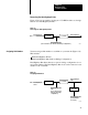
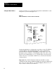
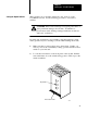
3. After you finish setting switches, push the removable frame back to
the operating position and tighten the four fasteners on the front of
the module. The fasteners must be tight to ensure that AC power is
not interrupted by the interlock switch on the power-supply board.
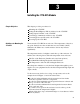
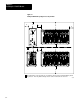
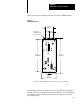
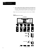
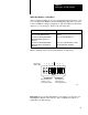
Figure 3.4 shows the switch-setting label on the side of the 1779-KP5.
Figure 3.4
SwitchSetting
Label on the 1779KP5
1779KP5/KP5R
Option Enabled
LEGEND
Option Disabled
1 2
6 7 8 9 10
3 4 5
11 12 13 14 15
White Is Depressed
LSB
LSB
DHII
DH+
Reserved 3
Reserved 4
S2
S4
S5
1
2
3
4
5
6
7
8
1
2
3
4
1
2
DH+ LINK
ADDRESS
DHII LINK
ADDRESS
ROUTE UPDATE
OPEN (OFF)
Not Used 230.4K 115.2K 57.6K
BAUD RATE SELECT
16484
ON OFF
ON OFF
ON
OFF