
Manual

Addressing from Data Highway Plus
Chapter 5
54
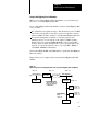
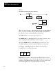
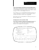
Data Highway Plus to a PLC3 (1779KP3, KP3R)
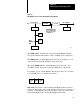
The following example shows a PLC-5 message instruction that reads 100
words of data from a PLC-3 (Data Highway II Link 00, Node 11), starting
at Memory Location B100:0. The command stores the data at Memory
Location N100:0 in the initiating PLC-5.
MESSAGE INSTRUCTION DATA ENTRY FOR CONTROL BLOCK N13:0
Read/Write: READ
PLC-5 Data Table Address:
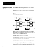
Press a key to change a parameter or <RETURN> to accept parameters.
[
Program No Forces No Edits PLC-515 ADDR 20
READ/
WRITE
F1
PLC-5
ADDRESS
F2
SIZE IN
ELEMENTS
F3
LOCAL/
REMOTE
F4
REMOTE
STATION
F5
LINK
ID
F6
Remote Station:
Link ID:
Remote Link Type:
Size in Elements:
Local/Remote:
Local Node Address:
Processor Type:
Destination Data Table Address:
N100:0
100
REMOTE
Node = 011 User = 001
00
DATA HIGHWAY II
50
PLC-3
B100:0
REMOTE
LINK
F7
LOCAL
NODE
F8
PROC.
TYPE
F9
DESTIN
ADDR
F10
BLOCK SIZE = 11 WORDS