
Manual

Addressing from Data Highway Plus
Chapter 5
512
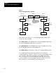
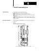
Figure 5.5
A
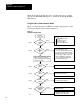
Remote Data Highway Plus Configuration
1779KP5 1779KP5
Data Highway Plus
Data Highway II
(Do not attach nodes
when used in bridge
configuration.)
Data Highway II
1779KP5
PLC5
Link 05
Link = 03
Node = 13
User = 01
Link = 03
Node = 45
User = 01
Link = 01 Link = 02 Link = 03
1779KP5
PLC5
Link 04
Link = 04
Node = 20
User = 01
Link = 01
Node = 50
User = 01
16497
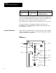
Since your Data Highway Plus link has a LINK number, the addressing
will work as follows:
The LINK number is the LINK number you have set on your
1779-KP5 for the Data Highway Plus link.
The NODE number is the destination node’s Data Highway Plus
address.
The USER number must be 1.
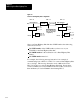
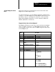
For example, the following message instruction is an example of
communicating from a PLC-5 to a PLC-5 on a remote Data Highway Plus
across a bridge. This message instruction reads 1,000 words from a
PLC-5, Node 013 on a remote Data Highway Plus link. It reads these
words from Memory Location N100:0 of the remote PLC-5 and stores
them in Memory Location N100:0 in the initiating PLC-5.